
Data Sheet


CC1101
SWRS061B Page 58 of 93
32.5 Continuous Transmissions
In data streaming applications the
CC1101
opens up for continuous transmissions at 500
kBaud effective data rate. As the modulation is
done with a closed loop PLL, there is no
limitation in the length of a transmission (open
loop modulation used in some transceivers
often prevents this kind of continuous data
streaming and reduces the effective data rate).
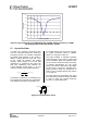
32.6 Crystal Drift Compensation
The
CC1101
has a very fine frequency
resolution (see Table 9). This feature can be
used to compensate for frequency offset and
drift.
The frequency offset between an ‘external’
transmitter and the receiver is measured in the
CC1101
and can be read back from the
FREQEST status register as described in
Section 14.1. The measured frequency offset
can be used to calibrate the frequency using
the ‘external’ transmitter as the reference. That
is, the received signal of the device will match
the receiver’s channel filter better. In the same
way the centre frequency of the transmitted
signal will match the ‘external’ transmitter’s
signal.
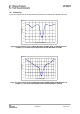
32.7 Spectrum Efficient Modulation
CC1101
also has the possibility to use Gaussian
shaped 2-FSK (GFSK). This spectrum-shaping
feature improves adjacent channel power
(ACP) and occupied bandwidth. In ‘true’ 2-FSK
systems with abrupt frequency shifting, the
spectrum is inherently broad. By making the
frequency shift ‘softer’, the spectrum can be
made significantly narrower. Thus, higher data
rates can be transmitted in the same
bandwidth using GFSK.
32.8 Low Cost Systems
As the
CC1101
provides 500 kBaud multi-
channel performance without any external
filters, a very low cost system can be made.
A differential antenna will eliminate the need
for a balun, and the DC biasing can be
achieved in the antenna topology, see Figure 3
and Figure 4.
A HC-49 type SMD crystal is used in the
CC1101EM reference designs ([5] and [6]).
Note that the crystal package strongly
influences the price. In a size constrained PCB
design a smaller, but more expensive, crystal
may be used.
32.9 Battery Operated Systems
In low power applications, the SLEEP state
with the crystal oscillator core switched off
should be used when the
CC1101
is not active.
It is possible to leave the crystal oscillator core
running in the SLEEP state if start-up time is
critical.
The WOR functionality should be used in low
power applications.
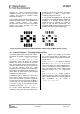
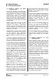
32.10 Increasing Output Power
In some applications it may be necessary to
extend the link range. Adding an external
power amplifier is the most effective way of
doing this.
The power amplifier should be inserted
between the antenna and the balun, and two
T/R switches are needed to disconnect the PA
in RX mode. See Figure 29.
Figure 29: Block Diagram of
CC1101
Usage with External Power Amplifier
CC11
0
1
Balun
Filter
A
ntenna
T/R
switch
T/R
switch
P
A