
Data Sheet


CC1101
SWRS061B Page 39 of 93
MAX_DVGA_GAIN value. This will reduce
power consumption in the receiver front end,
since the highest gain settings are avoided.
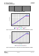
17.4.2 CS Relative Threshold
The relative threshold detects sudden changes
in the measured signal level. This setting is not
dependent on the absolute signal level and is
thus useful to detect signals in environments
with a time varying noise floor. The register
field AGCCTRL1.CARRIER_SENSE_REL_THR
is used to enable/disable relative CS, and to
select threshold of 6 dB, 10 dB, or 14 dB RSSI
change.
17.5 Clear Channel Assessment (CCA)
The Clear Channel Assessment (CCA) is used
to indicate if the current channel is free or
busy. The current CCA state is viewable on
any of the GDO pins by setting
IOCFGx.GDOx_ CFG=0x09.
MCSM1.CCA_MODE selects the mode to use
when determining CCA.
When the STX or SFSTXON command strobe is
given while
CC1101
is in the RX state, the TX or
FSTXON state is only entered if the clear
channel requirements are fulfilled. The chip will
otherwise remain in RX (if the channel
becomes available, the radio will not enter TX
or FSTXON state before a new strobe
command is sent on the SPI interface). This
feature is called TX-if-CCA. Four CCA
requirements can be programmed:
• Always (CCA disabled, always goes to TX)
• If RSSI is below threshold
• Unless currently receiving a packet
• Both the above (RSSI below threshold and
not currently receiving a packet)
17.6 Link Quality Indicator (LQI)
The Link Quality Indicator is a metric of the
current quality of the received signal. If
PKTCTRL1.APPEND_STATUS is enabled, the
value is automatically added to the last byte
appended after the payload. The value can
also be read from the LQI status register. The
LQI gives an estimate of how easily a received
signal can be demodulated by accumulating
the magnitude of the error between ideal
constellations and the received signal over the
64 symbols immediately following the sync
word. LQI is best used as a relative
measurement of the link quality (a high value
indicates a better link than what a low value
does), since the value is dependent on the
modulation format.
18 Forward Error Correction with Interleaving
18.1 Forward Error Correction (FEC)
CC1101
has built in support for Forward Error
Correction (FEC). To enable this option, set
MDMCFG1.FEC_EN to 1. FEC is only supported
in fixed packet length mode
(PKTCTRL0.LENGTH_CONFIG=0). FEC is
employed on the data field and CRC word in
order to reduce the gross bit error rate when
operating near the sensitivity limit.
Redundancy is added to the transmitted data
in such a way that the receiver can restore the
original data in the presence of some bit
errors.
The use of FEC allows correct reception at a
lower SNR, thus extending communication
range if the receiver bandwidth remains
constant. Alternatively, for a given SNR, using
FEC decreases the bit error rate (BER). As the
packet error rate (PER) is related to BER by:
lengthpacket
BERPER
_
)1(1 −−=
a lower BER can be used to allow longer
packets, or a higher percentage of packets of
a given length, to be transmitted successfully.
Finally, in realistic ISM radio environments,
transient and time-varying phenomena will
produce occasional errors even in otherwise
good reception conditions. FEC will mask such
errors and, combined with interleaving of the
coded data, even correct relatively long
periods of faulty reception (burst errors).
The FEC scheme adopted for
CC1101
is
convolutional coding, in which n bits are
generated based on k input bits and the m
most recent input bits, forming a code stream
able to withstand a certain number of bit errors
between each coding state (the m-bit window).