
Data Sheet


CC1101
SWRS061B Page 36 of 93
17 Received Signal Qualifiers and Link Quality Information
CC1101
has several qualifiers that can be used
to increase the likelihood that a valid sync
word is detected.
17.1 Sync Word Qualifier
If sync word detection in RX is enabled in
register MDMCFG2 the
CC1101
will not start filling
the RX FIFO and perform the packet filtering
described in Section 15.3 before a valid sync
word has been detected. The sync word
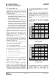
qualifier mode is set by MDMCFG2.SYNC_MODE
and is summarized in Table 24. Carrier sense
is described in Section 17.4.
MDMCFG2.
SYNC_MODE
Sync Word Qualifier Mode
000 No preamble/sync
001 15/16 sync word bits detected
010 16/16 sync word bits detected
011 30/32 sync word bits detected
100 No preamble/sync, carrier sense
above threshold
101 15/16 + carrier sense above threshold
110 16/16 + carrier sense above threshold
111 30/32 + carrier sense above threshold
Table 24: Sync Word Qualifier Mode
17.2 Preamble Quality Threshold (PQT)
The Preamble Quality Threshold (PQT) sync-
word qualifier adds the requirement that the
received sync word must be preceded with a
preamble with a quality above the
programmed threshold.
Another use of the preamble quality threshold
is as a qualifier for the optional RX termination
timer. See Section 19.7 on page 45 for details.
The preamble quality estimator increases an
internal counter by one each time a bit is
received that is different from the previous bit,
and decreases the counter by 8 each time a
bit is received that is the same as the last bit.
The threshold is configured with the register
field PKTCTRL1.PQT. A threshold of 4·PQT for
this counter is used to gate sync word
detection. By setting the value to zero, the
preamble quality qualifier of the synch word is
disabled.
A “Preamble Quality Reached” signal can be
observed on one of the GDO pins by setting
IOCFGx.GDOx_CFG=8. It is also possible to
determine if preamble quality is reached by
checking the PQT_REACHED bit in the
PKTSTATUS register. This signal / bit asserts
when the received signal exceeds the PQT.
17.3 RSSI
The RSSI value is an estimate of the signal
power level in the chosen channel. This value
is based on the current gain setting in the RX
chain and the measured signal level in the
channel.
In RX mode, the RSSI value can be read
continuously from the RSSI status register until
the demodulator detects a sync word (when
sync word detection is enabled). At that point
the RSSI readout value is frozen until the next
time the chip enters the RX state. The RSSI
value is in dBm with ½dB resolution. The RSSI
update rate, f
RSSI
, depends on the receiver
filter bandwidth (BW
channel
defined in Section
13) and AGCCTRL0.FILTER_LENGTH.
LENGTHFILTER
channel
RSSI
BW
f
_
28
2
⋅
⋅
=
If PKTCTRL1.APPEND_STATUS is enabled the
last RSSI value of the packet is automatically
added to the first byte appended after the
payload.
The RSSI value read from the RSSI status
register is a 2’s complement number. The
following procedure can be used to convert the
RSSI reading to an absolute power level
(RSSI_dBm).
1) Read the RSSI status register
2) Convert the reading from a hexadecimal
number to a decimal number (RSSI_dec)
3) If RSSI_dec ≥ 128 then RSSI_dBm =
(RSSI_dec - 256)/2 – RSSI_offset
4) Else if RSSI_dec < 128 then RSSI_dBm =
(RSSI_dec)/2 – RSSI_offset
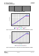
Table 25 gives typical values for the
RSSI_offset.
Figure 13 and Figure 14 shows typical plots of
RSSI reading as a function of input power
level for different data rates.