
Data Sheet

CC1101
SWRS061B Page 29 of 93
13 Receiver Channel Filter Bandwidth
In order to meet different channel width
requirements, the receiver channel filter is
programmable. The MDMCFG4.CHANBW_E and
MDMCFG4.CHANBW_M configuration registers
control the receiver channel filter bandwidth,
which scales with the crystal oscillator
frequency. The following formula gives the
relation between the register settings and the
channel filter bandwidth:
ECHANBW
XOSC
channel
MCHANBW
f
BW
_
2)·_4(8 +⋅
=
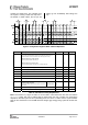
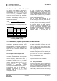
The
CC1101
supports the following channel filter
bandwidths:
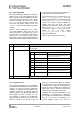
MDMCFG4.
MDMCFG4.CHANBW_E
CHANBW_M 00 01 10 11
00 812 406 203 102
01 650 325 162 81
10 541 270 135 68
11 464 232 116 58
Table 20: Channel Filter Bandwidths [kHz]
(Assuming a 26MHz crystal)
For best performance, the channel filter
bandwidth should be selected so that the
signal bandwidth occupies at most 80% of the
channel filter bandwidth. The channel centre
tolerance due to crystal accuracy should also
be subtracted from the signal bandwidth. The
following example illustrates this:
With the channel filter bandwidth set to
500 kHz, the signal should stay within 80% of
500 kHz, which is 400 kHz. Assuming
915 MHz frequency and ±20 ppm frequency
uncertainty for both the transmitting device and
the receiving device, the total frequency
uncertainty is ±40 ppm of 915MHz, which is
±37 kHz. If the whole transmitted signal
bandwidth is to be received within 400kHz, the
transmitted signal bandwidth should be
maximum 400kHz – 2·37 kHz, which is
326 kHz.
14 Demodulator, Symbol Synchronizer, and Data Decision
CC1101
contains an advanced and highly
configurable demodulator. Channel filtering
and frequency offset compensation is
performed digitally. To generate the RSSI level
(see Section 17.3 for more information) the
signal level in the channel is estimated. Data
filtering is also included for enhanced
performance.
14.1 Frequency Offset Compensation
When using 2-FSK, GFSK, or MSK
modulation, the demodulator will compensate
for the offset between the transmitter and
receiver frequency, within certain limits, by
estimating the centre of the received data.
This value is available in the FREQEST status
register. Writing the value from FREQEST into
FSCTRL0.FREQOFF the frequency
synthesizer is automatically adjusted
according to the estimated frequency offset.
The tracking range of the algorithm is
selectable as fractions of the channel
bandwidth with the FOCCFG.FOC_LIMIT
configuration register.
If the FOCCFG.FOC_BS_CS_GATE bit is set,
the offset compensator will freeze until carrier
sense asserts. This may be useful when the
radio is in RX for long periods with no traffic,
since the algorithm may drift to the boundaries
when trying to track noise.
The tracking loop has two gain factors, which
affects the settling time and noise sensitivity of
the algorithm. FOCCFG.FOC_PRE_K sets the
gain before the sync word is detected, and
FOCCFG.FOC_POST_K selects the gain after
the sync word has been found.
Note that frequency offset compensation is not
supported for ASK or OOK modulation.
14.2 Bit Synchronization
The bit synchronization algorithm extracts the
clock from the incoming symbols. The
algorithm requires that the expected data rate
is programmed as described in Section 12 on
page 28. Re-synchronization is performed
continuously to adjust for error in the incoming
symbol rate.