
Data Sheet

CC1101
SWRS061B Page 15 of 93
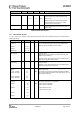
4.7 Analog Temperature Sensor
The characteristics of the analog temperature sensor at 3.0 V supply voltage are listed in Table 10
below. Note that it is necessary to write 0xBF to the PTEST register to use the analog temperature
sensor in the IDLE state.
Parameter Min Typ Max Unit Condition/Note
Output voltage at –40°C
0.651 V
Output voltage at 0°C
0.747 V
Output voltage at +40°C
0.847 V
Output voltage at +80°C
0.945 V
Temperature coefficient 2.45
mV/°C Fitted from –20 °C to +80 °C
Error in calculated
temperature, calibrated
-2
*
0 2
*
°C From –20 °C to +80 °C when using 2.45 mV / °C, after
1-point calibration at room temperature
*
The indicated minimum and maximum error with 1-
point calibration is based on simulated values for
typical process parameters
Current consumption
increase when enabled
0.3 mA
Table 10: Analog Temperature Sensor Parameters
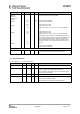
4.8 DC Characteristics
Tc = 25°C if nothing else stated.
Digital Inputs/Outputs Min Max Unit Condition
Logic "0" input voltage 0 0.7 V
Logic "1" input voltage VDD-0.7 VDD V
Logic "0" output voltage 0 0.5 V For up to 4 mA output current
Logic "1" output voltage VDD-0.3 VDD V For up to 4 mA output current
Logic "0" input current N/A –50 nA Input equals 0V
Logic "1" input current N/A 50 nA Input equals VDD
Table 11: DC Characteristics
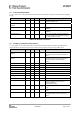
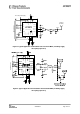
4.9 Power-On Reset
When the power supply complies with the requirements in Table 12 below, proper Power-On-Reset
functionality is guaranteed. Otherwise, the chip should be assumed to have unknown state until
transmitting an SRES strobe over the SPI interface. See Section 19.1 on page 41 for further details.
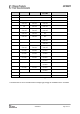
Parameter Min Typ Max Unit Condition/Note
Power-up ramp-up time. 5 ms From 0V until reaching 1.8V
Power off time 1 ms Minimum time between power-on and power-off
Table 12: Power-On Reset Requirements