
Data Sheet

CC1101
SWRS061B Page 12 of 93
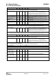
Table 5: RF Receive Section
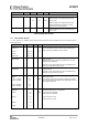
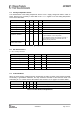
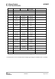
4.3 RF Transmit Section
Tc = 25°C, VDD = 3.0V, +10dBm if nothing else stated. All measurement results are obtained using the CC1101EM reference
designs ([5] and [6]).
Parameter Min Typ Max Unit Condition/Note
Differential load
impedance
315 MHz
433 MHz
868/915 MHz
122 + j31
116 + j41
86.5 + j43
Ω
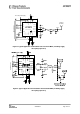
Differential impedance as seen from the RF-port (RF_P and
RF_N) towards the antenna. Follow the CC1101EM reference
design ([5] and [6]) available from theTI website.
Output power,
highest setting
+10
dBm Output power is programmable, and full range is available in all
frequency bands
(Output power may be restricted by regulatory limits. See also
Application Note AN039 [3].
Delivered to a 50Ω single-ended load via CC1101EM reference
design ([5] and [6]) RF matching network.
Output power,
lowest setting
-30
dBm Output power is programmable, and full range is available in all
frequency bands.
Delivered to a 50Ω single-ended load via CC1101EM reference
design([5] and [6]) RF matching network.
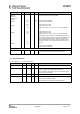
Harmonics,
radiated
2
nd
Harm, 433 MHz
3
rd
Harm, 433 MHz
2
nd
Harm, 868 MHz
3
rd
Harm, 868 MHz
-49
-40
-39
-64
dBm
Measured on CC1101EM reference designs([5] and [6]) with CW,
10dBm output power
The antennas used during the radiated measurements (SMAFF-
433 from R.W.Badland and Nearson S331 868/915) play a part in
attenuating the harmonics
Harmonics,
conducted
315 MHz
433 MHz
868 MHz
915 MHz
< -35
< -53
< -43
< -45
< -39
< -33
dBm
Measured with 10 dBm CW, TX frequency at 315.00 MHz,
433.00 MHz, 868.00 MHz, or 915.00 MHz
Frequencies below 960 MHz
Frequencies above 960 MHz
Frequencies below 1 GHz
Frequencies above 1 GHz
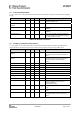
Parameter Min Typ Max Unit Condition/Note
General
Spurious emissions -68
-66
–57
–47
dBm
dBm
25 MHz – 1 GHz
(Maximum figure is the ETSI EN 300 220 limit)
Above 1 GHz
(Maximum figure is the ETSI EN 300 220 limit)
Typical radiated spurious emission is -49 dB
measured at the VCO frequency.
RX latency 9 bit Serial operation. Time from start of reception until
data is available on the receiver data output pin is
equal to 9 bit.