ELECRAFT K3 HIGH-PERFORMANCE 160 – 6 METER TRANSCEIVER K3 KIT ASSEMBLY MANUAL Rev M, September 3, 2014 Copyright © 2014, Elecraft, Inc.
Contents Introduction............................................................ 2 Customer Service and Support .................................. 3 Technical Assistance ............................................. 3 Preventing Electrostatic Discharge Damage ......... 5 How ESD Damage Occurs ........................................ 5 Preventing ESD Damage........................................... 5 Preparing for Assembly ......................................... 6 Overview of the Kit ..................
Key to Symbols and Text Styles Identifies important information. - 100 Characters displayed on the LCD screen DISP Tap switch function (labeled above a switch) AV E R AG E Hold switch function (labeled below a switch; hold for 1/2 sec.
Introduction This manual will guide you through assembly of your Elecraft K3 transceiver. We’re confident that you’ll find the K3 easy to build, even if you’ve had no prior kit-building experience. Every modern transceiver is complex, and the K3 is no exception. The kit includes nearly 300 individual components, including over a dozen PC boards and a multi-element modular chassis.
Elecraft's 1-Year Limited Warranty This warranty is effective as of the date of first consumer purchase (or if shipped from factory, date product is shipped to customer). It covers both our kits and fully assembled products. For kits, before requesting warranty service, you should fully complete the assembly, carefully following all instructions in the manual. Who is covered: This warranty covers the original owner of the Elecraft product as disclosed to Elecraft at the time of order.
Preventing Electrostatic Discharge Damage There is no climate or work location where the components of your K3 are safe from Electrostatic Discharge (ESD) unless you take specific steps to prevent such damage. Many of the components in your K3 can be damaged by static discharges of only a few volts: far too little for you to notice. It is those low-voltage but destructive discharges that easily happen anywhere and under virtually any environmental conditions. ESD damage may not be apparent at first.
We strongly recommend you take the following anti-static precautions (listed in order of importance) to avoid trouble: Leave ESD-sensitive parts in their anti-static packaging until you install them. The packaging may be a special plastic bag or the component’s leads may be inserted in conductive foam. Parts which are especially ESD-sensitive are identified in the parts list and in the assembly procedures. Wear a conductive wrist strap with a series 1-megohm resistor.
Figure 1. Typical Assembled K3/10 (Less Top Cover and Chassis Stiffener Bar).
Tools and Test Equipment Required 1. #0 and #1 size Phillips screwdrivers. To avoid damaging screws and nuts, do not use a power screwdriver. Use the screwdriver that best fits the screw in each step. 2. Soft cloth or other surface to lay cabinet panels on to avoid scratching. A clean static-dissipating mat is ideal (see below). If using cloth, do not lay circuit boards on it. See Preventing Electrostatic Discharge Damage on page 5. 3. Pliers or suitable wrenches for tightening 1/4”, 3/16” and 1/2” nuts.
Unpacking and Inventory CAUTION Do not handle the circuit boards without anti-static protection! Doing so may damage sensitive components. See Preventing Electrostatic Discharge Damage on page 5 for important information before proceeding. Before starting construction, do a complete inventory, comparing the parts in your kit with the parts list in Appendix A, to familiarize yourself with all of the parts and to ensure the kit is complete.
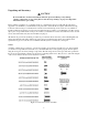
Standoffs A number of threaded standoffs are used. As with the screws and washers, be sure you use the correct size as specified in the text. Standoff lengths are measured from end to end as shown in Figure 3. Standoffs threaded for 2-56 and 4-40 screws are used. Figure 3. Typical Standoff. Lock Washers Two types of lock washers are used in the K3 (see Figure 4). It is important that you use only the type specified and put the washers exactly where indicated.
Assembly IMPORTANT ASSEMBLY INFORMATION 1. Screws and other Fasteners: A variety of screws and fasteners are used to assemble your K3: Stainless Steel Hardware Kit: If you purchased the optional hardware kit that provides stainless steel hardware for the external fasteners, the letters (SS) are included in the procedure wherever you should use the stainless steel parts instead of the parts supplied with this kit. Use your rule to check the length of screws and standoffs before installing them.
RF Board and Chassis RF Board Description The RF PCB (Printed Circuit Board) is the heart of the K3 transceiver, both physically and electrically. During assembly, it serves as an attachment point for other PCBs as well as chassis panels, acting as the glue that holds things together. During operation, the RF board provides signal routing to and from all modules. For more information, see Theory of Operation, RF Board, in the K3 Owner’s Manual.
Install a 4-40 3/8” (9.5 mm) standoff on the RF board near connector Z1 as shown in below and Figure 11 on page 16. This standoff will support the mixer to be installed later. Install the standoff using three lock washers as shown below with two of the lock washers between the standoff and the RF board.
Install hardware to attach Q3 to the RF board near the rear left corner as shown in Figure 9 and Figure 11 on page 16. Figure 9. Installing Q3 Hardware. Locate the crystal I.F. filters. Two types of filters are available: standard 5-pole filters and optional 8-pole filters (see Figure 10). One standard 5-pole 2.7 kHz filter is supplied. If you have elected to equip your K3 with the optional 8-pole 2.8 kHz filter, it has been supplied instead of the 2.7 kHz filter.
Install the filters as shown in Figure 10. Refer to the list of filters you created in Table 1 to determine which filter to install at each location. CAUTION 1) Do not use screws longer than 1/4” (6.4 mm) to mount the filters. Use your ruler to measure the screws before installing them. Longer screws may extend into the optional 8pole filter and destroy it.
Figure 11. RF Board Partially Assembled.
Install the Low Power Amplifier (LPA) board in the cutout on the RF board as shown in Figure 12. The LPA board is held in place by its connectors until the bottom cover is installed.. Figure 12. Installing the Low Power Amplifier (LPA). Check all three LPA connectors shown in Figure 12 to ensure they are fully mated as shown. If they are not fully mated, the transistors will not rest against the K3 bottom cover as required when it is fitted later.
Mount a 2D fastener on each ear of the front panel shield, and then mount the shield on the RF board as shown in Figure 13. Be sure the 2D fasteners are oriented with the widest part between the two holes and the edge toward the outside as shown. Figure 13. Installing Front Panel Shield. Mount the K3 mixer board on the RF board as shown in Figure 14. The mixer plugs into Z1 on the RF board. Figure 14. Installing Mixer Board.
Locate the two side panels. They are approximately 4” (10 cm) by 9-7/8” (25 cm) in size. Both panels have six counter-sunk screw holes near the edges. Note that the countersunk holes are farther from one end than the other. This is important. You will need to orient the panels correctly as you install them. The side panels are different as well.
Mount a 2D fastener at the top back corner of the left side panel (the one you just installed) with a 4-40 3/16” (4.8 mm) black flat head screw (SS) as shown in Figure 17. Do not use washers. Be sure the 2D fastener is oriented correctly as shown in the figure. Figure 17. Installing Left Side Panel 2D Fastener. KANT3 or KAT3, Right Side and Rear Panels If you purchased a KAT3 with your kit, you did not get a KANT3 board with your kit. For more information, see the KANT3 AND KAT3 Circuit Description below.
If you have the KRX3 Subreceiver option kit on hand, you may wish to install the AUX RF antenna connector at this time. The AUX RF connector is one optional way to connect an antenna to the subreceiver. Before you decide, turn to your KRX3 Installation and Operation Manual and review the Auxiliary KRX3 Antenna Input (Optional) section. It is not necessary to install the connector now, even if you decide to use it. Complete instructions for installing it later are included in your KRX3 manual.
Thread the BNC/TMP cable through the AUX RF connector hole from the outside, lining up the flat on the threaded section of the connector with the flat at the top of the hole. Slide the lock washer and nut onto the cable. Fold the solder lug on the braid down against the coax to fit through the back panel hole, the lock washer and the nut. Thread the nut onto the connector and tighten it (see Figure 20). Mount the solder lug attached to the braid as shown in Figure 20, using a 4-40 3/8” (9.
Preparing Right Side Panel for Installation Install the four rubber side feet in the holes in the right side panel as shown in Figure 21. Two suggested procedures for doing this are as follows: Press Method: Twist Method: Wet the tip of the foot with a tiny amount of soap. (Do not use petroleum jelly or oils. They can deteriorate the rubber over time). Press the foot against the outside (fully painted side) of the panel so the tip is in the hole at an angle.
At the upper rear corner of the side panel you just identified in the previous step, mount a 2D fastener as shown in Figure 22, using a black 4-40 1/2” (13 mm) flat head screw (SS). Remember that flat head screws are measured from the flat top to the end of the threads. Note that the screw extends some distance through the 2D fastener. Figure 22. Mounting 2D fastener for KANT3 or KAT3 Standoff. Screw a 4-40 1/2” (13 mm) standoff onto the exposed end of the screw as shown in Figure 23.
Peel the backing from the self-adhesive serial number label and attach it to the back panel as shown in Figure 25. You may wait until the assembly is finished before attaching the serial number, but at this point you can lay the panel flat on the work surface to easily position the label square within the outline. Figure 25. Attaching Serial Number. Position the rear panel on the K3 chassis assembly so that the SO239 connector(s) are at the end nearest the KANT3 or KAT3 board.
Connect the wires from the SO239 connector(s) to the KANT3 or KAT3 board as shown in Figure 28. Use needle-nose pliers to grip the terminals on the wire ends and carefully insert the connectors straight into the holes in the board. They may be very difficult to insert unless they are perfectly aligned. While inserting the plugs, support the board with your fingers to avoid putting stress on the connector at the bottom. Figure 28. ANT Connections to KANT3 or KAT3 Boards.
If you installed the KANT3 board, the hole for the ANT2 jack is not used. Insert the larger of the hole plugs in the opening until it clicks in place (see Figure 30). If you do not have the K3EXREF option, insert one of the smaller hole plugs in the REF connector at the bottom right. Align the open side of the plug with the flat side of the hole as shown in Figure 30. If the plug does not have a cutout, use your diagonal cutters to clip out a section of the plug so it will fit into the hole.
Mount two 1-1/4” (31.8 mm) standoffs in the two holes on the KIO3 board as shown in Figure 33 using a zinc 4-40 1/4” (6.4 mm) screw and inside tooth lock washer at each standoff. One is in the corner and the other is about half way down the opposite side of the board. Do not put lock washers between the standoffs and the board. Inspect the KIO3 Audio board for a yellow dot at one corner of the board (see below). There are two versions of the audio board, one with a yellow dot and one without.
Install the KIO3 Main board with the Audio I/O daughter board attached into the K3 as shown in Figure 34. The KIO3A main board plugs into J76 on the RF board. If the KXV3 is installed, the coaxial TMP cable fits between the KXV3 and KIO3 boards. Ensure the connectors are fully mated so the standoffs line up with the screw holes on the rear panel. Figure 34. Installing KIO3 Main Board. The DB9 multi-pin connector on the KIO3 Digital I/O daughter board may have jackscrew nuts installed on the connector.
Install the KIO3 rear panel as shown in Figure 36. Figure 36. Mounting the KIO3 Connector Panel.
Front Panel and DSP Front Panel and DSP Description The Front Panel is a large plug-in module that provides the K3’s user interface (LCD, switches, shaft encoders, potentiometers, and LEDs) as well as the microcontroller (MCU) and parameter storage (EEPROM and FLASH). It also includes the 32-bit DSP assembly, which processes all AF and IF signals. See Theory of Operation, Front Panel and DSP, in the K3 Owner’s Manual.
On the front side of the board, mount four standoffs as shown in Figure 38. IMPORTANT! 1. Place the split lock washers between the standoff and board as shown in the figure. This is important to establish the correct spacing between the board and the front panel. 2. Note that the two standoffs near the LCD use smaller #2 hardware. Figure 38. Preparing the Front Panel Board for Mounting, Part 2. Inspect the front panel board to verify the following: Three 4-40 5/8” (15.
Install the two soft foam light blockers at the ends of the LCD display as shown in Figure 39. Remove the paper strip covering the adhesive on each blocker and stick that side against the board (or the lip at the base of the switch buttons) so it stands up between the switches and the LCD. Push them down so the adhesive side is against the board or base of the switches and that they cover ends of the LCD, including the terminals at the right hand end of the LCD as shown. Figure 39.
Ensure the flange on the MIC connector is not caught behind the panel. The flange should be slightly above the panel as shown all the way around its circumference as shown in Figure 41. It may be a snug fit requiring you to press it into place, pushing on the back of the connector. If the connector refuses to fit through the hole in the front panel, use a sharp tool to carefully remove the paint from the inside edge where the connector is binding against the hole.
Place the VFO A encoder in the opening near the center of the front panel board so the shaft protrudes through the opening under the LCD. Be careful to avoid dropping the lock washer into to the space between the front panel board and the front panel. Normally, the lock washer hangs on the threads while you put the encoder in place. Optionally, you can hold the encoder with the shaft upright and place the front-panel assembly over it until the shaft is through the hole.
CAUTION! In the following steps you will attach the plastic LCD cover and VFO A trim panels to the front cover using small screws. Use the screws specified in each step. Do not over-tighten these screws. Tighten the screws only to the point where you feel some resistance. It is very easy to strip the threads, especially the screws holding the LCD cover.
Mount the cover on the front panel over the LCD as shown in Figure 47 oriented so the beveled edges are away from the panel. If the cover seems to bind against the VFO A trim panel, rotate it so the long edge striking the trim panel is at the top and, if necessary, work the screws through the holes in the plastic cover some more to loosen the fit. Tighten the screws only until they come into firm contact with the trim panel. Be sure you are using screws no longer than 5/32” (4.
CAUTION! You may damage the encoders while installing the knobs in the next step unless you align the flats in the knobs with the flats on the shafts as described below. Press small knobs on the four controls under the left end of the LCD: SHIFT/LOW, HI/WIDTH, SPEED/MIC and CMP/PWR. These knobs are all the same size and are held in place by a friction spring as shown in Figure 49. Align the flat in the knob with the flat on each shaft before pressing each knob in place.
Mount the last knob on the VFO B encoder shaft to the right (under the pushbutton switches) as shown in Figure 51. Before tightening both set screws, adjust the position of the knob against the felt washer to produce the desired amount of drag for smooth movement without the knob turning too freely. Figure 51. Mounting the VFO B Knob. Mounting the Subreceiver Auxiliary DSP Board If you purchased the optional KRX3 Subreceiver with your K3, install the KXR3 auxiliary DSP board as follows.
Mount the three 7/16” (11mm) male/female standoffs on the component side of the main DSP board as shown in Figure 53 using 4-40 nuts and #4 split lock washers. Be sure that: The standoffs are on the component side of the board as shown. No lock washer is used between the standoff and the board. One split lock washer is used between the nut and the board. Figure 53. Installing Standoffs on the Main DSP Board.
Locate resistor R3 on the front panel board (mounted on the front panel). If R3 is positioned above the board on its leads as shown in Figure 55, push it over to one side of the outline as shown. Be sure you don’t push it so far its leads might touch the solder pads for other components on the board. Figure 55. Positioning R3 on the Front Panel Board. Installing the KDVR3 Digital Voice Recorder Option If you have the KDVR3, install it on the main DSP board as shown in Figure 56.
Mounting the DSP Board Assembly on the Front Panel Locate the main DSP board and install the nylon standoff near J51 as shown below. Be sure you place it in the correct hole near the edge of the board. The standoff is also shown in Figure 56. CAUTION: To avoid damaging a circuit trace very close to the metal ring around the screw hole, position the lock washer under the screw so the split faces away from the trace.
Squeeze the boards together while ensuring the pins are mating with the connectors until the DSP board is resting against the three standoffs on the back of the front panel board that you installed earlier. The two connectors will not mate completely. About 1/4” (6.4mm) of the pins may be visible when the DSP board is positioned against the standoffs.
Screw the knurled nut onto the threaded shaft of the PHONES jack where it exits the front panel (see Figure 60). Screw it only finger tight. Do not use pliers. Figure 60. Phones Jack Hardware. Mounting the Front Panel Assembly Remove both side panels from the chassis as follows. This will allow you to see the connectors that must mate properly when attaching the front panel assembly. Remove the two screws shown in Figure 61 so the 2D connector and standoff remain attached to the side panel.
ESD SENSITIVE: Wear a grounded wrist strap or touch an unpainted metal ground before handling the RF Board in the following steps. Turn the chassis upside down and position the front panel so the pins of P30 and P35 on the bottom of the RF board just begin to engage the connectors on the lower edge of the front panel assembly. Do not fully mate them yet. Figure 62. Mounting Front Panel Assembly - Connectors P30 and P35.
REMOVING THE FRONT PANEL: If you need to remove the front panel assembly, remove the five screws holding it to the chassis (three on the top lip and two on the bottom), turn the unit upside down and use a screwdriver in the two pry slots provided as shown in Figure 64. Do not insert the screwdriver deep enough to strike components on the boards! Pry each end in short increments until the connectors separate. Either a blade (as shown) or Phillips screwdriver may be used.
Attach voltage regulators U13 and U12 to the right side panel as shown in Figure 65 using a 4-40 3/8” (9.5 mm) black flat head screw (SS), #4 inside tooth lock washer and a #4 nut for each regulator as shown. When the screws are tightened the tabs on U12 and U13 should lie flat against the side panel. Figure 65. Attaching U12 and U13 to the Right Side Panel.
Resistance Checks The following resistance checks confirm that the main power busses in the K3 aren’t shorted to ground. If any of the values measured are lower than specified, inspect the unit carefully for loose hardware that is caught between components on the boards or for improperly mated connectors. Use your digital multimeter (DMM) to measure the resistance across the red and black 12VDC IN connectors on the rear panel. The resistance should be greater than 3K ohms.
Initial Power On Check The following check confirms that the power supply and power control circuits are working properly. Be sure your K3 passes the resistance tests above before proceeding. CAUTION! If you see or smell smoke when applying power, turn the K3 off and remove the power cable immediately, then locate the source. Connect your 13.8 VDC power supply to the 12VDC IN connector on the rear panel. If you do not have a suitable cable handy, assemble the Power Supply Cable Kit supplied with your K3.
Mount the TCXO module on the KREF3 board as shown in Figure 69. Be certain the leads go into the corner holes in the socket and the black dot is oriented toward connector J6 as shown. If you have a 1ppm high-stability module, the dot may be light brown and not as close to the corner. If the module has only three leads, the missing lead will be in the corner with the dot. If you have the standard 5ppm TCXO, the bottom may be slightly above the socket when the leads are fully inserted.
CAUTION In the following step it is easy to drop screws and lock washers into the K3. If this happens, you must find and retrieve the hardware. Failing to do so may cause short circuits and damage your K3 when power is applied. Recommend you practice installing the KREF3 board without the screw and washers first to acquaint yourself with the procedure for inserting it and fitting the connector through the hole in the front panel shield. You’ll need to do this smoothly to avoid dropping the hardware.
KSYN3 Synthesizer KSYN3 Description The KSYN3 module is a high-performance, wide-range synthesizer covering 8 to 46 MHz. It uses a crystalfiltered DDS (direct digital synthesis) reference. This in turn drives a VCO with a high C/L ratio, resulting in very low phase noise. See Theory of Operation, KSYN3, in the K3 Owner’s Manual for more information. The KSYN3 is supplied with a stiff metal plate covering the front of the pc board.
CAUTION In the following step it is easy to drop screws and lock washers into the K3. If this happens, you must find and retrieve the hardware. Failing to do so may cause short circuits and damage your K3 when power is applied. Install the KSYN3 board on the back side of the front panel shield using the hardware exactly as shown in Figure 74. This is most easily done as follows: Place an inside tooth lock washer over each 1/2” (12 mm) pan head screw, then place the screw in the hole in the KSYN3 board.
Locate the three TMP cables. They are about 1/8” (3 mm) diameter coaxial cables with connectors at each end as shown in Figure 75. Check each cable and trim any excess center conductor strands extending beyond the end of the pin as shown. This will make mating the connectors much easier. Figure 75. TMP Cable Connectors. Install the three TMP cables between connectors on the KREF3 board, the main RF board and the KSYN3 board as follows.
Loudspeaker Loudspeaker Description The built-in loudspeaker is mounted on the top cover. A grill cloth covering the sound holes keeps dust and debris from falling into the speaker cone. The loudspeaker is equipped with a magnetic shield to avoid unwanted interaction with nearby circuits. Loudspeaker Installation Procedure Locate the top cover and check the inside for any masking tape still covering screw holes. If found, peel it off.
Mount the speaker using the hardware shown in Figure 78. A suggested procedure for doing this is as follows: Find a book or other flat-smooth surface that is about the size of the top cover. From the top, place the screws in the four holes at the corners of the speaker grill area. Cover the screw heads with the book and, holding it in place against the top cover, invert the cover and lay it with the book on your work table so the bottom side is facing upwards.
Install the shield over the speaker magnet as shown in Figure 79. Figure 79. Installing Speaker Magnet Shield. KPA3 Shield If you are not planning to install the KPA3 module at this time, skip this section and go directly to Bottom Cover on page 59. Only the KPA3 shield is installed at this time to avoid rework later. You will be directed to finish installing the KPA3 module after initial testing and calibration of your K3.
Attach the shield to the RF board and to the rear panel as shown in Figure 81. The screws, washers and nut are in the KPA3 Option kit. The standoffs are part of the K3 kit hardware. Figure 81. Attaching the KPA3 Shield. Remove the stiffener bar from the top cover and install it on the chassis as shown in Figure 82. The hardware required to attach it to the shield are in the KPA3 Option kit. The black flat head screws used to attach it to the side panels are part of the K3 kit hardware. Figure 82.
Bottom Cover Bottom Cover Description The bottom cover is divided into two parts, the rear and forward sections. The rear section is slightly thicker than the forward section to act more efficiently as a heat sink for the LPA transistors. The bottom covers attach to standoffs as well as the 2D fasteners on the bottom of the RF Board. A folding tilt stand and feet are mounted on the cover panels.
Identify the bottom cover forward section by test fitting it on the bottom of the K3. The forward section is the thinner panel with a notch along one edge (see Figure 84). One side of the cover is fully painted. That is the outside. The other side has areas of bare metal left to ensure good electrical contact with the other cabinet parts. Check the inside surface for any masking tape left from the painting process. If found, peel it off.
Locate the rear bottom cover section. This cover has eight rectangular slots cut in it. Like the front section, bare metal is exposed in some areas on the inside surface. The bare metal ensures good electrical contact with the other cabinet parts and good thermal contact with the heat sinks for Q2, Q4 and Q5 on the LPA circuit board. Check the inside surface of the bottom cover for any masking tape that may have been left from the painting process. If found, peel it off.
Plug the noise blanker board into J77 and attach it to the standoff using the hardware shown in Figure 87. Figure 87. Installing the Noise Blanker Board. Battery BT1 Battery BT1 Description BT1 is a 3-volt lithium coin cell that provides the operating voltage for the real-time-clock IC (RTC) on the front panel when the K3 is turned off. Depending on the type of cell, BT1 could last from 2 to 10 years, thanks to the extremely low current drain of the RTC – on the order of a few microamperes.
KBPF3 General Coverage Receive Option If you have the KBPF3 General Coverage Receive option kit, install the board as follows. Otherwise skip this section and go directly to Power Amplifier Jumper Block on page 64. KBPF3 Description The KBPF3 extends the receive coverage outside of the Ham bands over the range of 500 KHz to 30 MHz and from 48 MHz through 54 MHz. Only the receiver coverage is extended. The transmitter frequency coverage is not affected.
Power Amplifier Jumper Block The Power Amplifier (PA) jumper block is required to operate the K3 without the optional KPA3 100 watt power amplifier module installed. Your RF board was shipped with the jumper block installed. Even if you are planning to install the KPA3 at this time, do not remove it until instructed to do so. You will be performing some essential tests and calibration procedures before the KPA3 module is installed.
Bottom Covers Turn the K3 over so the bottom is exposed. Position the forward section of the bottom cover with the feet and bail toward the front as shown in Figure 91. Attach the cover with seven 3/16” (4.8 mm) black pan head screws (SS) at the positions shown. Do not use washers. Figure 91. Installing Bottom Cover Forward Section. Locate the three thermal pads and clear the screw holes. They are already cut.
Install the rear bottom cover section as follows (see Figure 93): Position the cover so the holes near the center line up with the transistors on the LPA board. The remaining holes will line up with 2D fasteners and standoffs. Note: The bottom cover is anodized, not painted. There is a circular area around the three holes on the inside surface that was masked to retain the bare metal. This circular area may not cover the entire area of the thermal pads of all three transistors. That is normal.
Top Cover Even if you have the KPA3 100-watt module to install, install the top cover and speaker at this time for initial testing and calibration of the basic 10-watt K3 configuration. Connect the speaker cable to P25 of the KIO3 board as shown in Figure 94. If you have the KPA3 shield installed, route the speaker wire under the stiffener bar. Figure 94. Connecting Speaker to KIO3 Board. Place the top cover on the K3 with the tab at the rear extending under the lip of the rear panel.
If you have the KPA3 shield installed, place three 4-40 3/16” (4.8 mm) black flat head screws (SS) through the holes across the middle of the cover to secure it to the stiffening bar. If you have not installed the KPA3 shield, the stiffening bar is still attached to the top cover where you mounted it to measure the speaker grill cloth for trimming. Place a 4-40 3/16” (4.8 mm) black flat head screw (SS) into each side panel to secure the ends of the stiffening bar. .
Test and Calibration It’s time to apply power! In the following tests and procedures you will check out and calibrate essential functions of your basic K3. You must complete these procedures before operating your K3 at low power or before installing a KPA3 100-watt power amplifier option. Have your K3 Owner’s Manual handy. Detailed procedures are in your Owner’s Manual where you can find them easily in the future if you need them.
If you checked the “Yellow Dot” box on page 28 while inspecting the KIO3 Audio Board, do the following. Otherwise skip this step and proceed to Synthesizer Calibration below. The headphone jack on the KIO3 Audio Board uses an inverted speaker cut-off logic that prevents speaker audio with the default firmware setting. Change the firmware setting as follows: Hold the C O N F I G switch at least 1/2 second to bring up the configuration menu on the LCD.
Filter Setup Turn to the Crystal Filter Installation and Setup section of your Owner’s Manual and perform the following procedures. If you have installed standard Elecraft 5-pole filter(s) you will need the FREQ OFFSET data you recorded earlier on page 14. Filter Bandwidth Setup Filter Center Frequency Setup Receive Filter Enables Filter Loss Compensation Transmit Filter Selection The transmit filter selection setup requires that you select a valid transmit filter for each mode.
Option Modules Enable Modules Enable the KNB3 noise blanker and, if installed, the KBPF3, KAT3, KDVR3 and KXV3 option modules as described in the Option Module Enables section of your Owner’s Manual. Even though they are installed, these modules will not function until they are enabled. KPA3 100-Watt Amplifier Installation If you purchased the KPA3 100-watt amplifier option, turn to the KPA3 Option Installation Instructions manual Installation Procedure to complete installation and testing now.
Appendix A Illustrated Parts List Your kit contains a number of envelopes, boxes and packages of parts. Check the contents of each one carefully against the following lists. Doing so will not only ensure no parts are missing, but it will also familiarize you with the appearance of each part that helps the kit assembly go smoothly and quickly. You may find extra small parts included in your kit. The quantities specific are those required. Also there is a small bag marked Spares containing more extra parts.
E850323 KREF3 TCXO Module Bag QTY ELECRAFT PART NO. This module is not supplied if you purchased the optional ±1 ppm module shown below. . 1 E660033 Tie Wrap, KREF3 TCXO. Module 1 E980145 DESCRIPTION QTY ELECRAFT PART NO. KREF3 TCXO Module, 49.380 MHz, ±1 ppm stability. (optional) 1 KTCXO3-1 TCXO spacer (supplied only with optional KTCXO3-1 module) 1 E980146 Tie Wrap, KREF3 TCXO. Module 1 E980145 QTY ELECRAFT PART NO. 1 E850249 Screw, 4-40, either 1/4” (6.4 mm) Zinc, Pan Head.
Optional Filter QTY ELECRAFT PART NO. KFL3A-2.8K Filter (optional) 1 KFL3A-2.8K Screw, 4-40, either 1/4” (6.4 mm) Zinc, Pan screw in envelope. 1 E700005 Lock Washer, #4, Interior Tooth in envelope with screw. 1 E700010 ILLUSTRATION DESCRIPTION If you ordered additional crystal filters, they will be enclosed in the box in separate bags with the same hardware shown above.
ILLUSTRATION DESCRIPTION K3 DSP Printed Circuit Board Assembly QTY ELECRAFT PART NO. 1 E850233 1 E850256 1 E850257 ESD Sensitive LPA (Low Power Amplifier) PCB Assembly ESD Sensitive. K3 Mixer PCB Assembly ESD Sensitive.
ILLUSTRATION DESCRIPTION QTY ELECRAFT PART NO. KNB3 Noise Blanker PCB Assembly 1 E850280 1 E850254 1 E850402 ESD Sensitive. KREF3 PCB Assembly ESD Sensitive.
ILLUSTRATION DESCRIPTION QTY ELECRAFT PART NO. 1 E850237 1 E850649 1 E850235 KIO3 Main PCB Assembly ESD Sensitive. KIO3 Audio I/O PCB Assembly ESD Sensitive. NOTE: The board may have a yellow dot near one corner. This is normal and explained in the assembly procedure. KIO3 Digital I/O PCB Assembly ESD Sensitive.
Miscellaneous Components Packed in separate bags and envelopes as follows: E850239 K3 FP Encoder Assembly Bag QTY ELECRAFT PART NO. 2 E850239 QTY ELECRAFT PART NO. Knob, VFO B Tuning 1 E980090 Knob, RIT/XIT 1 E980089 Knob, Concentric Shaft, Large 2 E980092 Knob, Concentric Shaft, Small 2 E980091 QTY ELECRAFT PART NO.
E850306 K3 Knob and Band for VFO A (bag) QTY ELECRAFT PART NO. Knob, VFO A Tuning 1 E980093 Finger Grip, Main VFO Tuning Knob 1 E980094 QTY ELECRAFT PART NO.
E850263 K3 RF Misc. Bag You will find bags included inside this bag. Where a bag or envelope inside this bag contain several parts with individual part numbers, they are listed on separate tables following this one. In addition there is a small bag marked K3 Hardware Spares Bag. It contains a collection of small parts that are easily lost. Normally you will not need any of the parts it contains to build your kit. QTY ELECRAFT PART NO.
Typical Standoffs (May be round or hexagonal) Typical Pan Head Screws Zinc Black Standoff, 4-40, 1/4” (6.4 mm) long 6 E700026 Standoff, 4-40, 3/8” (9.5 mm) long 2 E700153 Standoff, 4-40, 1/2” (13 mm) long 3 E700061 Screw, 4-40, 3/16” (4.8 mm) Black, Flat Head 27 E700025 Screw, 4-40, 3/8” (9.5 mm) Black, Flat Head 6 E700131 Screw, 4-40, 1/2” (13 mm) Black, Flat Head 1 E700132 Screw, 4-40, 3/16” (4.8 mm), Black, Pan Head 38 E700015 Screw, 4-40, 1/4” (6.
E850067 Allen Wrench Envelope (in K3 RF Misc Bag) QTY ELECRAFT PART NO. Allen Wrench, 5/64” (in envelope) 1 E980004 Allen Wrench, .050” (in envelope) 1 E980006 QTY ELECRAFT PART NO. Screw, 6-32, 1/4” (6.4 mm) Black Flat Head 3 E700186 Lock Washer, #6, Split Ring 3 E700041 Nut, 6-32 3 E700040 QTY ELECRAFT PART NO. Screw, 4-40 1/2” (12 mm) Zinc, Pan Head 2 E700196 Screw, 4-40 3/8” (9.
E850229 SO239 Ant Connector Assembly Bag (in K3 RF Misc Bag) QTY ELECRAFT PART NO. SO239 (UHF) Female Panel Mount Connector with cable 1 E850229 Screw, 4-40, 1/4” (6.4 mm) Black, Pan Head 2 E700009 Lock Washer, #4, Inside Tooth 2 E700010 Nut, 4-40 2 E700011 QTY ELECRAFT PART NO. Screw, 4-40, 1/4” (6.4 mm) Black, Pan Head 4 E700009 Screw, 4-40, 1/4” (6.
E850241 Front Panel Hardware Bag QTY ELECRAFT PART NO. Felt Washer 3 E700033 Knurled Nut (Phones Jack) 1 E700138 Standoff, 2/56, 5/16” (7.9 mm) long 2 E700122 Standoff, 4-40, 5/16” (7.9 mm) long 2 E700121 Standoff, 4-40, 5/8” (15.9 mm) long 3 E700003 Standoff, Nylon, 5/8” (15.9 mm) long 1 E700163 Screw, 4-40, 3/16” (4.8 mm) Black, Flat Head 1 E700025 Screw, 2-56, 1/4” (6.4 mm) Black, Pan Head 2 E700124 Screw, 4-40, 1/4” (6.
E850341 VFO A Bezel Screws Envelope (in Front Panel Hardware Bag) Do not mix these screws up with other parts in the Front Panel Hardware bag. Confusing them with other screws nearly the same length may destroy your front panel board. They are packaged separately for your convenience. You will be instructed when to use each screw in the assembly procedure. DESCRIPTION QTY ELECRAFT PART NO. Screw, 4-40, 5/16” (7.9 mm) Black, Flat Head 1 E700027 Screw, 2-56, 1/4” (6.
E850350 K3 RF BSF Assembly (in box) RF Board 1 E850557 1 E850325 ESD Sensitive PA Jumper Block Assembly (pre-installed on RF board) A-15
E850262 K3 Chassis Set (in box) ILLUSTRATION QTY ELECRAFT PART NO.
E850312 Side Panels QTY ELECRAFT PART NO. Left Side Panel 1 E100210 Right Side Panel 1 E100211 QTY ELECRAFT PART NO. Bottom Cover A 1 E100213 Bottom Cover B 1 E100221 DESCRIPTION QTY ELECRAFT PART NO.