
User Guide

12/14/2017 Elecfreaks Motor:bit User Guide – ElecFreaks – Devote to open hardware.
https://www.elecfreaks.com/11703.html 4/9
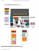
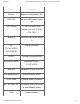
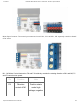
Type Instruction
Buzzer Buzzer is controlled by P0.
LED COL Micro:bit LED matrix control
pin
VCC Switch 3.3V/5V electric level
switch only for P13-P16,
P19, P20.
Button-A Micro:bit main board button
A
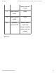
P4-
P7,P9,P10,P13-
P16,P19,P20
Digital connecotr
P4,P10 Analog connector/PWM
SCK MISO MOSI Hardware SPI pin -
P13,P14,P15
SDA SCL Hardware IIC pin -P19,P20
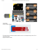
The power switch External power switch
6-12V GND External power connector
M1+ M1- M2+ M2- Connector of two DC motor
or one stepping motor.
PWR Power Indicator