
Operating Instructions and Installation Instructions


ULTRAMAX PB 65 - 120
59 L290 ©MHS Boilers 13/12/2010
Appendix E
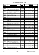
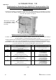
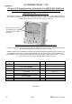
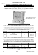
Balanced Flue Terminal Positions For Boilers Below and above 70kW Net Input
All measurements are in mm and are minimum clearances.
Terminal Location
Boilers with a rated Input < 70kW Net
Boilers with a rated Input > 70kW Net
A
*Below and opening window etc.
300
600
B
Below gutter soil pipes etc.
75
700
C
Below Eaves.
200
200
D
*Below balconies or carport
roof.
200
N/A
E
From vertical drain or soil pipe
etc.
150
150
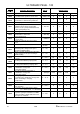
F
From internal or external
corners.
300
300
G
Above ground or balcony level.
300
300 (2000 where people have general
access)
H
From a surface facing the
terminal.
2000
2000
I
From a terminal facing
the terminal.
2000
2000
J
*From opening in a carport
into a dwelling.
1200
N/A
K
Vertically from a terminal on
the same wall.
1500
1500
L
Horizontally from a terminal on
the same wall.
300
600
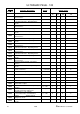
M
Above an opening, window etc.
500
600
N
*Horizontally to an opening,
window etc.
300
600
P
Above a level roof
(base of terminal.)
500
500
Q
From an adjacent wall
(edge of terminal.)
500
500
R
From adjacent opening, window
etc.
1000
1000
S
From any other flue terminal.
600
600
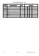
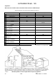
* Positions not recommended.
Groups of appliances of 150kW gross input (136kW net input) and above must comply with the Clean Air
Act with respect to the chimney discharge height. The terminal/s shall be guarded if it is less than 2000mm
above the ground or in any position where it may cause injury to persons resulting from touching a hot
surface. Absolute guidance must be sought from the respective regulation.