
Operating Instructions and Installation Instructions


ULTRAMAX PB 65 - 120
57 L290 ©MHS Boilers 13/12/2010
Ultramax PB Supplementary Information For OCI420 LPB
Communication Installation Including LMU64 and RVA47 Controller
reprogramming. (Part Code. 96.38000-7004)
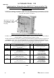
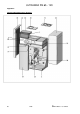
Following the installation of the OCI420 LPB communication clip (complete with base mounted wiring
connection) onto the front of the LMU64 controller a number of operational parameters within the unit must be
altered to ensure the clips operates as required.
LMU64 Pictured above with AGU2.511 and OCI420 communication clips.
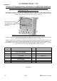
A number of parameters will require altering within the LMU64 controller from their standard default setting to
allow the OCI420 communication clip to operate correctly.
Access is gained to the H parameters by pressing the PROG ▲▼ buttons simultaneously for 3 seconds unit
H 90 appears on the screen. The required H parameters can then be reached by using the PROG ▲. Or
PROG ▼buttons. Once at the required H parameter the required setting is achieved by using the + - buttons.
To save the alteration in the controller the INFO button must be pressed.
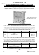
A number of parameters will require altering within the RVA47 cascade controller from their standard default
setting to allow the RVA47 to operate correctly.
Access is gained to the operational parameters of the RVA47 cascade controller by pressing the PROG ▲▼
buttons simultaneously for 3 seconds unit 51 appears on the screen. The required parameters can then be
reached by using the PROG ▲. Or PROG ▼buttons. Once at the required parameter the required setting is
achieved by using the + - buttons. To save the alteration in the controller the AUTO button must be pressed.
Please note that the QAC32 outside air sensor must be connected to the RVA47 cascade controller.
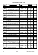
L OCI.
LMU
Parameter #
Description
Default
New Setting
H516
External temperature at which the boiler ceases to
operate in heating mode. Summer / Winter changeover
temperature.
18
30
H552
System hydraulic configuration.
66
80
H605
Boiler positioning in cascade
1
Boiler # 1 = 2
Boiler # 2 = 3
etc up to boiler #12 = 13
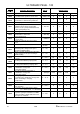
RVA47
Parameter #
Description
Default
New Setting
16
External temperature at which the boilers cease to
operate in heating mode. Summer / Winter changeover
temperature.
17
30
140
Cascade Communication Master Configuration
1
1
141
Cascade communication Master Configuration
0
0
148
Cascade communication Clock Configuration
3
3
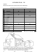
Appendix C
Cascade wiring connection point
X41. Polarity must be observed.