
Operating Instructions and Installation Instructions

ULTRAMAX PB 65 - 120
43 L290 ©MHS Boilers 13/12/2010
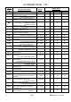
18.0 Information Display
18.1 Via AGU 2.311 Operating Panel
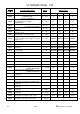
Parameters of Groups b, c and d are provided upon request only.
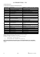
Display Level
LMU Functional ID
Description
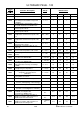
Temperatures (specialist level)
b 0
Diagnose Code
LMU internal SW diagnostics code
b 1
TkRuec
Boiler return temperature
b 2
Tbwist2
Reservoir temperature at sensor 2 (non existent)
b 3
Tabgas
Exhaust temperature
b 4
TiAussen
Exterior temperature
b 5
TaGem
Mixed exterior temperature
b 6
TaGed
Dampened exterior temperature
b 7
Tvist
Flow temperature AGU 2.500
b 8
Not assigned
b 9
Not assigned
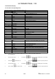
Process values (specialist level)
c 0
Not assigned
c 1
IonStrom
Ionisation flow
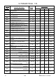
c 2
Gebl_Drehz
Blower rpb
c 3
Gebl_PWM_AusAkt
Current blower control (PWM)
c 4
RelModLevel
Relative output
c 5
Pump_PWM
Pump target value (PWM)
c 6
Ek0
Control difference
c 7
Not assigned
c 8
Not assigned
c 9
Not assigned
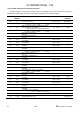
Target values (specialist level)
d 0
Not assigned
d 1
Tsoll
Target value for 2-point and modulating control valve (PID)
d 2
TkSoll
Current boiler target value
d 3
RsRaum
Room temperature target value
d 4
TbwSoll
Reservoir target value
d 5
PhezMax
Maximum degree of modulation during heating mode
d 6
NhzMax
Maximum rpm at maximum output during heating mode.
d 7
Not assigned
d 8
Not assigned
d 9
Not assigned
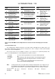
Note: By either pushing the “mode” button or waiting for 8 minutes, the display automatically reverts back to
the standard display.
1. Push information button. 2 Push buttons
for at least 3 seconds until b0 appears in the display.
3 Push button
then alter b0 to c0 4 Push buttons to select the respective parameter.
1. Push information button. 2 Push buttons
for at least 3 seconds until b0 appears in the display.
3 Push 2 x button
then alter b0 to d0 4 Push buttons to select the respective parameter.