
Operating Instructions and Installation Instructions

ULTRAMAX PB 65 - 120
3 L290 ©MHS Boilers 13/12/2010
7.0 Gas connection
24
8.0 Mounting the exterior
temperature sensor
25
9.0 Electrical Installation
25
9.1 General Notes
25
9.2 Dimensioning of power connection wiring
26
9.3 Power connection and connection of customer- provided
wiring.
26
9.4 Terminal layout
27
10.0 Commissioning
28
10.1 Re-circulation Pump
29
10.2 Control Measures
29
10.3 Minimum circulation amounts / Flow monitoring
29
10.4 Ensure prior to commissioning
29
10.5 Description of Control Valve Stop Function.
30
10.6 Trigger.
30
10.7 Function.
30
10.8 Settings
30
10.9 Adjustment of combustion quality
31
10.10 Adjustment values for Natural Gas.
31
10.11 Conversion from Natural Gas to LPG.
31
10.12 Adjustment values for liquid gas.
31
10.13 Switch Panel and AGU Operating Panel
32
10.14 AGU Operating Panel
33
10.15 AGU Operating Panel (continued)
34
10.16 Information Button
34
10.17 Adjustment of Target Temperature for Heating Circuit
35
10.18 Adjustment of Target Temperature for Domestic Hot
Water “DHWTarget”
35
11.0 Parameterisation (End
User)
36
11.1 Adjustment for individual End User Requirements
36
11.2 Parameterisation for End User
37
12.0 Clock Function
38
12.1 Effect
38
12.2 Description of Domestic Use Water Provision
38
12.3 Operating Mode
38
12.4 Effect
38
13.0 Function upon
Attached Room Device
QAA73 (Accessory)
38
14.0 Backlight
39
15.0 Maintenance and
Service
39
16.0 Cleaning
40
16.1 Disassembly of the Burner
40
16.2 Cleaning the Burner and Fan
40
16.3 Cleaning the Heat Exchanger
41
17.0 Error Message List
42
17.1 Error Messages Displayed via AGU Operating Panel
42
18.0 Information Display
43
18.1 Via AGU 2.311 Operating Panel
43
19.0 Level One Parameters
Review and Alternation
44
20.0 Reviewing LMU64
Operating Error Codes
45
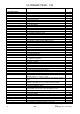
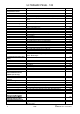
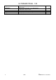
22.0 Full Parameters List
46 - 54
Appendix A
Supplementary information on the AUG 2.511 communication
clip-in module.
55