
Operating Instructions and Installation Instructions

ULTRAMAX PB 65 - 120
26 L290 ©MHS Boilers 13/12/2010
9.0 Electrical Installation cont.
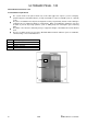
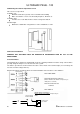
9.2 Wiring
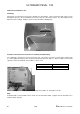
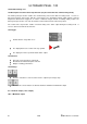
All external connection wires must not be stripped more than 30mm. The hot lead from strain relief to cleats
must tighten up before the grounded wire in case they slip out of the strain relief (2). The wire length must be
dimensioned accordingly. All wires must be routed around the dividing plate.
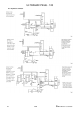
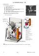
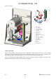
9.3 Power connection and connection of customer-provided wiring.
The equipment is designed for a fixed connection only. The power connection is made at the terminal strip
(1) of the equipment using a power circuit intended and fused for this purpose. All pole switches and contact
opening of >3mm or automatic cutout switches can be used.
Power consumption system pump(s) Max. switching current LMU 1A / relay Max. 5 A total.
Note:
If Ultramax PB is operated with a mixer circuit connected via AGU 2.500, a jumper must be installed across
terminals 50/51 (X10-01).
Line voltage
230 V, 50 Hz
Power connection fuse
10 A
Power consumption
Max. 420 W