
Operating Instructions and Installation Instructions

ULTRAMAX PB 65 - 120
25 L290 ©MHS Boilers 13/12/2010
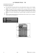
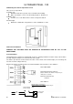
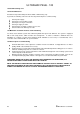
8.0 Mounting the exterior temperature sensor
This sensor is not pre-wired.
Installation site:
Minimum of 2m above ground, on the north wall of the building
Make sure that the sensor is not affected by fireplaces, windows etc
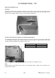
Installation type:
Turn the sensor such that the wires exit the casing at the bottom
Conduit length:
Maximum of 100m when using NYM 3 x 1 mm² or H05W-F3 x 1 mm²
9.0 Electrical Installation
WARNING THIS APPLIANCE MUST BE EARTHED IN ACCORDANCE WITH BS 7671 and IEE
REGULATIONS
9.1 General Notes
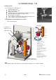
The Ultramax PB is supplied as standard with electronic operating and flame ionisation safety controls with a
specially designed microprocessor at the heart of the system.
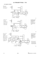
The boiler is pre-wired as shown and all connections can be made on the terminal strips (one low voltage 25
vac and one mains voltage 240 v ac).
Electrical specialists should perform the electrical installation and connections to the appliance.
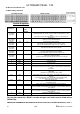
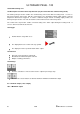
54-55 Safety Interlock Volt Free
(Must be wired in series with the low pressure gas
switch please see below)
52-53 Room thermostat
Volt Free
56-57 NOT USED
50-51 QAA 73
Low pressure
gas switch
Volt free Safety
Interlock Circuit
55
54
Safety Interlock Volt Free
(Must be wired in series with the low pressure gas
switch)