
Operating Instructions and Installation Instructions

ULTRAMAX PB 65 - 120
16 L290 ©MHS Boilers 13/12/2010
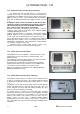
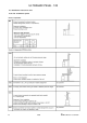
4.2 Installation of internal hydraulic pressure switch
In order to protect the boiler / plate heat exchanger primary circuit from operating under conditions of low
water pressure, a minimum water pressure switch kit has been developed and is now available as an
additional optional extra item. Please ensure that this item is specified / included whenever a boiler protection
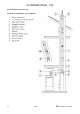
plate heat exchanger set is utilised with the Ultramax PB Boiler. As can be seen from the diagram below, the
pressure switch is mounted to a tee piece, which is attached via the primary drain cock tapping.
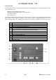
4.3 Siphon and condensate discharge
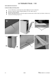
Insert siphon (1) according to the Figure below.
Dismount cover panelling from condensing boiler.
Connect condensate discharge to a foul water drain or a neutralizing device (accessory) to the
siphon.
Note:
The condensate must be able to freely drip into a funnel. The condense pipework must be acid resistant and
connected to the foul water drain.
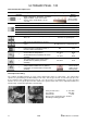
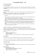
4.4 Flue Installation Options
For the installation of the exhaust system, please pay attention to the respective local regulations.
Installation example
for a separate
condensate
discharge from the
exhaust vent
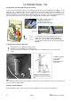
To electrically connect the minimum water pressure
switch (10); remove and discard the link between
terminals 1 & 2 on the main terminal strip within the
boiler and connect the switch as shown in the adjacent
diagrams
The cables from the pressure
switch to the terminal rail
should be routed via the
grommet circled in the image.