
Operating Instructions and Installation Instructions

ULTRAMAX PB 65 - 120
13 L290 ©MHS Boilers 13/12/2010
2.0 Production Description cont.
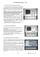
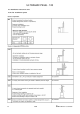
Button
No of
Presses
Description
Options / Range
Recommended
Setting
1 - 4
Mode of Operation. „Automatic‟, „Constant‟,
„Night Set-Back‟, „OFF, frost control‟.
(Cursor under symbol dictates mode
selected).
Automatic
(Cursor under
Clock Symbol).
1
Actual Boiler Flow temperature.
Review Only
Review Only
2
Actual Stored Hot Water.
Review Only
Review Only
3
Not Used
Not Used
Not Used
4
Boiler Operation Function Number.
Review Only
Review Only
5
Actual Outside Air Temperature
Review Only
Review Only
6
Fault Code Indication.
E-00…..E-999
Review Only
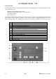
For access of the control programs, Day,
Time, etc.
Selection of operating line
Buttons for the adjustment of selected
values
Re-adjustment of set-up parameters
1
Full System Reset following a Fault, or
Customer Induced fault E153.
N/A
N/A
1
Maximum Heating Temperature, or
Assumed Room Temperature
{If Outside Air Sensor (QAC34) has been
installed}
20 - 85ºC
or
10 - 30ºC
80ºC
or
20ºC
1
Stored Hot Water Target Temperature.
{If HWS Sensor (QAZ21) has been
installed}
20 - 60ºC
55ºC
1
Hot Water Selection On/Off.
{Only available if HWS Sensor (QAZ21)
connected, or Volt Free Stat is in Demand
position}.
On
(Cursor under
symbol under
TAP Symbol).
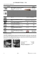
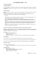
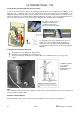
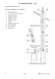
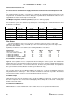
2.9 Compact Gas Fitting
The compact gas fitting functions as a gas safety shutoff valve and as a control valve. The control valve
operates as a pneumatic gas/air differential pressure valve. On the gas exit side, it controls the gas pressure
P
0
as a function of the combustion air pressure P
L
. If no air pressure is accumulated (P
L
= 0), the gas valve
remains closed. The gas/air pressure ratio and thus the gas/air volume ratio can be adjusted and therefore
remain nearly constant throughout the set load range.
Safety shutoff valves 2, class B/C
Line Voltage 239 VAC
Current load 0,37A
Gas pressure monitoring set to 10 mbar
Gas fitting including gas filter