
Operating Instructions and Installation Instructions

ULTRAMAX PB 65 - 120
10 L290 ©MHS Boilers 13/12/2010
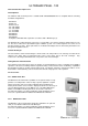
2.74 OCI420 Clip-In Module LPB Communication
With the use of an OCI420 Clip-In Module, the Optional Extra Controls
detailed from 17.5 onwards can also be utilized.
One Clip-In Module is required per boiler in a Multiple Boiler arrangement.
Please refer to instructions supplied with the Clip-In Module for
programming instructions (Ref. - LOCI).
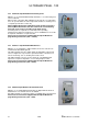
2.72 AGU2.500 Clip-In Module Extra Heating Zone
With the use of an AGU2.500A109 Clip-In Module, a second heating zone
can be activated.
When used in conjunction with a QAA73 Room Unit, this second heating
zone can operate under the same temperature dictates as heating zone 1,
or separately under time control only.
When a QAA73 Room Unit is NOT being used, the RU connections
(X10-01) MUST be linked so the time clock for the second heating
zone time clock can be accessible via the boiler fascia.
If a mixing value is required to accommodate lower operating
temperatures from that of Heating Zone 1, then a QAD36 flow sensor will
be required, available as an optional extra.
Please refer to instructions supplied with the Clip-In Module for
programming instructions (Ref. – LAGU2).
2.73 AGU2.511 Clip-In Module BMS Interface
With the use of an AGU2.511 Clip-In Module, the boiler controller can
communicate with a BMS System.
This Clip-In Module has three 240V (50Hz) programmable outputs that
can be configured to respond to the operational status of the boiler, for
remote monitoring, such as, Healthy, Run and Lockout.
This Clip-In Module can also accept a 0-10V dc or 0-20mAmp input
signals for Set-point Temperature, or Percentage Output control.
Please refer to instructions supplied with the Clip-In Module for
programming instructions (Ref. - LAGU).