Ultramax PB 65 - 120 Floor Standing Condensing Boiler Operating & Maintenance Manual MHS Boilers Ltd. 3 Juniper West Fenton Way Basildon Essex SS15 6SJ Telephone 01268 546700 Fax 01268888270 WWW.MHSBOILERS.
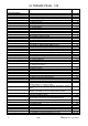
ULTRAMAX PB 65 - 120 2–3-4 Table of Contents 1.0 General Notes 1.1 Conformity Statement 1.2 Installation Requirements 1.3 Hot Water Quality 1.4 Unknown Water Quality and Exchanger Systems 1.5 Existing System 1.6 Scope of Delivery 2.0 Product Description 2.1 Technical Data 2.2 Dimension Diagram 2.3 Components 2.4 Compliance 2.5 Heat Exchanger 2.6 Regulation and Control Unit 2.7 Accessories 2.71 QAA73 Room Unit Interface (OpenTherm) 2.711 QAA70 Room Unit 2.72 AGU2.500 Clip-In Module Extra Heating Zone 2.
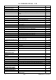
ULTRAMAX PB 65 - 120 7.0 Gas connection 8.0 Mounting the exterior temperature sensor 9.0 Electrical Installation 24 25 9.1 General Notes 9.2 Dimensioning of power connection wiring 9.3 Power connection and connection of customer- provided wiring. 9.4 Terminal layout 10.0 Commissioning 10.1 Re-circulation Pump 10.2 Control Measures 10.3 Minimum circulation amounts / Flow monitoring 10.4 Ensure prior to commissioning 10.5 Description of Control Valve Stop Function. 10.6 Trigger. 10.7 Function. 10.
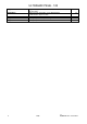
ULTRAMAX PB 65 - 120 Appendix B Appendix C Appendix D Appendix E Appendix F 4 Supplementary information on the AUG 2.500 communication clip-in module. Supplementary information on the OCI420 LPB communication clip-in module.
ULTRAMAX PB 65 - 120 1.0 General Notes These instructions are intended to assist the installer; commissioning engineer, maintenance engineer and the user with the application and usage of the Ultramax PB floor standing gas fired condensing boilers. Please read this manual carefully before commencing the installation, maintenance or commissioning of the appliance. Failure to strictly observe these instructions may invalidate the warranty or prevent the appliance from operating correctly.
ULTRAMAX PB 65 - 120 The following Codes of Practice are also applicable: BS 5449:1990 Specification for forced circulation hot water central heating systems for domestic premises. BS 6644:2005 Specification for gas fired hot water boilers of rated inputs between 70kW (net) and nd rd 1.8MW(net) (2 and 3 family gases). BS 6880:1988 Code of Practice for low temperature hot water heating systems of output greater than 45kW. Parts 1,2 & 3.
ULTRAMAX PB 65 - 120 2.0 PRODUCT DESCRIPTION 2.1 Technical Data Ultramax Boiler Model PB 65 PB 85 Product Identification Number PB 100 PB 120 0063BQ3008 Gas Category 112ELL3P / 112H3P Nominal Heat Output 80/60C kW 8.4 - 60.0 15.6-77.8 17.6-88.2 21.9-109.8 Nominal Heat Output 40/30C kW 9.4-65.0 17.0-85.0 19.2-96.3 24.0-120.0 Nominal Heat Input Net kW 8.6 - 60.7 16.0 - 80.0 18.0 - 90.0 22.5 - 112.4 Gas Input Natural Gas G20 m3/h 6.28 8.28 9.32 11.65 Gas Input LPG G31 m3/h 2.
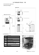
ULTRAMAX PB 65 - 120 2.0 Production Description cont. 2.2 Dimension Diagram Dimensions Minimum Clearances Cable entry 2.
ULTRAMAX PB 65 - 120 2.0 Production Description cont. 2.4 Compliance The Ultramax PB condensing boiler is identified with CE-0063BQ3008 and is compliant with the following standards and guidelines. - DN EN 677 EN 60 335 EN 55 014-1/2 90 / 396 / EWG 89 / 336 / EWG 73 / 23 / EWG 92 / 42 / EWG DIN EN 483 DIN EN 297 DIN EN 656 Compliance with NOx limits required in accordance with 1 BlmSchV§7 (2). The Ultramax PB condensing boiler represents a system with a closed heat exchanger independent of room air.
ULTRAMAX PB 65 - 120 2.72 AGU2.500 Clip-In Module Extra Heating Zone With the use of an AGU2.500A109 Clip-In Module, a second heating zone can be activated. When used in conjunction with a QAA73 Room Unit, this second heating zone can operate under the same temperature dictates as heating zone 1, or separately under time control only.
ULTRAMAX PB 65 - 120 2.75 RVA47 Cascade Controller (Grey) & Housing The RVA47 Cascade Controller (Grey) is a comprehensive unit that can be wall or control panel mounted. The RVA47 is supplied with 2 No QAD21 System Sensors (flow & return) and a QAC32 outside air sensor. Each Ultramax PB boiler MUST be fitted with an OCI420 Communication Clip-In Module, see item 17.4.
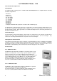
ULTRAMAX PB 65 - 120 2.8 Control Panel The switch panel and all of the above operating elements are integrated into the condensing boiler. The LMU system electronics offer: - Management of modulating boiler control Weather-regulated heating control for 1 heating circuit Hot water generation Outside Air Sensor The hot water temperature is factory preset to 55°C but can be changed. The heating circuit characteristics are preset and can be adjusted according to the respective system.
ULTRAMAX PB 65 - 120 2.0 Production Description cont. Button No of Presses Description Options / Range Recommended Setting 1 Mode of Operation. „Automatic‟, „Constant‟, „Night Set-Back‟, „OFF, frost control‟. (Cursor under symbol dictates mode selected). Actual Boiler Flow temperature. Review Only Review Only 2 Actual Stored Hot Water. Review Only Review Only 3 Not Used Not Used Not Used 4 5 Boiler Operation Function Number.
ULTRAMAX PB 65 - 120 3.0 General Requirements 3.1 Condensing Boiler In condensing boilers, residual heat is extracted from the exhaust gases through cooling and condensation and subsequently fed back into the heating system. This ensures a high degree of efficiency and low energy consumption. 3.2 Chimney Notes Exhaust vents must be installed in a shaft or chimney compliant with the prevailing Standards and Codes of Practice.
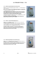
ULTRAMAX PB 65 - 120 4.0 Installation instructions 4.1 Disassembly of boiler panels Loosen Allen bolt (1) at front panel (2). Exert slight pressure to front panel. Pull the front panel forward and pull upward out of the retainer clip (3). Pull off top panel upwards. Remove side panels (4+5) to the bottom right and left from the retainer clips (6) and take off at the top via the two fastening tongues (7).
ULTRAMAX PB 65 - 120 4.2 Installation of internal hydraulic pressure switch In order to protect the boiler / plate heat exchanger primary circuit from operating under conditions of low water pressure, a minimum water pressure switch kit has been developed and is now available as an additional optional extra item. Please ensure that this item is specified / included whenever a boiler protection plate heat exchanger set is utilised with the Ultramax PB Boiler.
ULTRAMAX PB 65 - 120 4.0 Installation instructions cont. 4.5 Connection to air/exhaust system through an existing chimney. For the concentric air/exhaust system, use original accessory parts only, including the PPS exhaust system lubricant available. Gas condensing boilers with an air/exhaust system via an existing chimney to the roof must be installed in the attic or in rooms in which the ceiling is also the roof, or where the only thing above the ceiling is the roof construction.
ULTRAMAX PB 65 - 120 4.0 Installation instructions cont. 4.9 Room Air Independent flue arrangement.
ULTRAMAX PB 65 - 120 4.0 Installation instructions cont. 4.
ULTRAMAX PB 65 - 120 4.0 Installation instructions cont. 4.11 Connection to a combustion air supply and exhaust system C63x not tested in conjunction with gas boiler. The straight air/exhaust system for connection to a combustion air supply and exhaust system must not be longer than 2m. A maximum number of three 90° angles are permitted for the installation. If combustion air is supplied from the shaft, it must be kept free from any dirt. 4.
ULTRAMAX PB 65 - 120 4.0 Installation instructions cont. 4.16 Installation requirements The system shall not be placed inside any rooms with aggressive vapours (such as hairspray, perchloroethylene, tetracarbonchlorine) or high accumulation of dust or humidity (such as a laundry room). The place of installation must be protected against freezing. Any warranty shall be void for damages resulting from non-compliance with these requirements.
ULTRAMAX PB 65 - 120 5.
ULTRAMAX PB 65 - 120 6.0 Filling system Connect water hose to KFE valve (2). Open all radiator valves. Fill cold system up to 1 bar. Monitor water quality. Ventilate pump (loosen impeller with screwdriver if necessary). Fill condensate siphon with water (approx. 0.5L). Start-up pump several times. Upon completion venting, fill system to final operating pressure. Close venting screw and remove filling hose. 6.
ULTRAMAX PB 65 - 120 Low Loss Header 7.0 Gas connection Authorised gas installers must perform the layout of gas pipes and connection to the gas line only. Heating and gas lines must be cleaned from any residue, particularly for older systems, prior to the connection of the gas condensing boiler. Care must be taken to ensure a non-stressed layout of all gas lines. Prior to commissioning, all pipe conduits and connections must be checked for tightness and leaks.
ULTRAMAX PB 65 - 120 8.0 Mounting the exterior temperature sensor This sensor is not pre-wired. Installation site: Minimum of 2m above ground, on the north wall of the building Make sure that the sensor is not affected by fireplaces, windows etc Installation type: Turn the sensor such that the wires exit the casing at the bottom Conduit length: Maximum of 100m when using NYM 3 x 1 mm² or H05W-F3 x 1 mm² 9.
ULTRAMAX PB 65 - 120 9.0 Electrical Installation cont. 9.2 Wiring All external connection wires must not be stripped more than 30mm. The hot lead from strain relief to cleats must tighten up before the grounded wire in case they slip out of the strain relief (2). The wire length must be dimensioned accordingly. All wires must be routed around the dividing plate. 9.3 Power connection and connection of customer-provided wiring. The equipment is designed for a fixed connection only.
ULTRAMAX PB 65 - 120 9.0 Electrical Installation cont. Boiler Wiring Terminals 9.4 Boiler Wiring Terminals Terminal Designation Terminal #s Voltage Description/Operation/Function Screened Cable (Earthed Yes Screening) 50 & 51 (Not Polarity Sensitive) < 25V 52 & 53 (Not Polarity Sensitive) 54 & 55 (Not Polarity Sensitive) < 25V Yes < 25V Yes Safety Interlock Volt Free Enable (Must be wired in series with the low pressure gas switch) (For use with ventilation interlocks/gas pressure switch etc.
ULTRAMAX PB 65 - 120 10.0 Commissioning 10.
ULTRAMAX PB 65 - 120 10.0 Commissioning cont. 10.2 Control Measures An authorised specialist shall perform the initial commissioning only. In general, the following control checks must be performed prior to commissioning: Check power supply. Check pressure in heating system. Check pressure at gas connection. Check gas supply for leaks. Check proper assembly of exhaust accessories. Check condensate discharge for leaks. 10.
ULTRAMAX PB 65 - 120 10.0 Commissioning cont 10.5 Description of Control Valve Stop Function (To place the boiler into commissioning mode) The chimneysweeper function enables the commissioning of the boiler while in heating mode. It serves to take measurements at the boiler, with the system being set to maximum heating output until the overheat temperature thermostat is triggered.
ULTRAMAX PB 65 - 120 10.9 Adjustment of combustion quality Connect equipment in terms of water, gas and electricity. Due to the different ignition features of natural gas LL and natural gas E, an adjustment of the gas/air mixture is required. After ignition, the specified CO2 value at full load can be adjusted by turning the adjustment screw (2). Adjustment of the CO2 value at small load by turning the adjustment screw (1) at the gas fitting. 10.10 Adjustment values for Natural Gas.
ULTRAMAX PB 65 - 120 10.0 Commissioning cont. 10.13 Switch Panel and AGU Operating Panel Ultramax PB Button Operating Element Function 1 Button Reset (unlock) Unlocking LMU… Ignition manager 2 Button Domestic water use mode Domestic water use ON/OFF 3 Button Set mode heating circuit Switch operating mode to: Automatic mode Continuous mode at nominal level Continuous mode at reduced level Frost protection 4 Button Target temp.
ULTRAMAX PB 65 - 120 10.0 Commissioning cont. 10.
ULTRAMAX PB 65 - 120 10.0 Commissioning cont. 10.15 AGU Operating Panel Display 1 2 3 4 5 7 8 9 Operating modes for heating circuit Operating modes for domestic use water Heating circuit operating mode (day/night) Time Current boiler value Flame status Time bar Boiler operating mode 10.16 Information Button Pushing the information button will switch you into the information level. Further activation of the information button calls up various information available at this level.
ULTRAMAX PB 65 - 120 10.0 Commissioning cont. 10.17 Adjustment of Target Temperature for Heating Circuit. The target value for room temperature or boiler temperature is adjusted depending on the heating system! If no buttons are pushed during an approximate 8 min time period, the system automatically reverts back to the standard display, and any changes are not saved.
ULTRAMAX PB 65 - 120 11.0 Parameterisation for End User 11.1 Adjustment for individual End User Requirements If no buttons are pushed during an approximate 8-minute time period, the system automatically reverts back to the standard display. No changes are saved. Button Description 1 Push one of the two line selector buttons. They take you directly to the “End User” level 2 Use one of the line selector buttons to advance to the respective line.
ULTRAMAX PB 65 - 120 11.0 Parameterisation for End User 11.2 Parameterisation Item AGU2.
ULTRAMAX PB 65 - 120 12.0 Clock Function The timer must be set to the correct time in order to provide the correct heating program operation. The current time is set as described on the previous page (Parameterisation End User). 12.1 Effect Clock is set to the current time. The correct setting is important to ensure that the heating and domestic hot water program can function properly. Notes Clock continues to run during the adjustment process.
ULTRAMAX PB 65 - 120 14.0 Backlight Upon activation of any button, the backlight is activated for a period of approx. 8 minutes. 15.0 Maintenance and Service Trained and authorised personnel only must perform maintenance and cleaning. Said personnel shall bear all responsibility for their proper implementation. Important Equipment must be isolated from the Electrical supply, Gas supply, flow and return supplies before commencing any maintenance or service work. Maintenance shall be performed once a year.
ULTRAMAX PB 65 - 120 16.0 Cleaning 16.1 Disassembly of Burner Remove electrical plug-on HT and Ignition caps. Remove earth lead. Loosen bolts (1) at fan unit (2). Loosen mounting bolts (3) at burner unit (4). Remove burner unit completely from heat exchanger. 16.2 Cleaning of Burner and Fan Perform visual inspection of burner (4) and fan (2). Any dirt intrusion from the air supply are typically blown and burnt through the burner under normal equipment use.
ULTRAMAX PB 65 - 120 16.0 Cleaning cont. 16.3 Cleaning of Heat Exchanger With the Burner removed, visually check the interior of the heat exchanger. Any deposits on the surface of the stainless steel coils must be gently removed with a natural bristle brush. For stubborn deposits, cleaning granules are available from MHS Boilers Spares department.
ULTRAMAX PB 65 - 120 17.0 Error Message List 17.1 Error Messages Displayed via AGU Operating Panel Display flashes Code No.
ULTRAMAX PB 65 - 120 18.0 Information Display 18.1 Via AGU 2.311 Operating Panel Parameters of Groups b, c and d are provided upon request only.
ULTRAMAX PB 65 - 120 19.0 Level One Parameters Review and Alternation A limited number of (Customer) parameter levels are available via the control panel, these parameters are as listed in table below, and can be accessed by using the ▲ & ▼ Program Buttons.
ULTRAMAX PB 65 - 120 20.0 Reviewing LMU64 Operating Error Codes As an extension of the Standard ERROR Codes, the LMU64 also records Operating ERROR Codes, which can be accessed by at Service / Commissioning Engineer. To access the Operating ERROR Codes, „Press & Hold‟ the ▲ & ▼ Buttons, for approximately 3 seconds. H 90 will appear, then use the ▲ or ▼ Buttons to reference the Parameter Line ID Number detailed below.
ULTRAMAX PB 65 - 120 Fault Code Description Fault Code 83 Combustion Fan Not Reaching Ignition Speed 87 Combustion Fan Operating Beneath Minimum Setting 90 96 97 98 99 100 101 102 Description 170 RESET Button is Being Continually Depressed 259 RESET Button Has Been Pressed When NO Error Has Been Displayed 282 Combustion Fan Not Reaching Correct Speed Fault Code 406 Combustion Fan Not Reaching Pre-Purge Speed.
ULTRAMAX PB 65 - 120 Display or QAA73 # H90 H91 H93 H94 H501 H502 H503 H504 H505 H506 H507 H508 H509 H510 H511 H512 H513 H514 H515 H516 H517 H518 H519 H520 H521 47 Function / Description Reduced Temperature for DHW 8….60 DHW Production Control 0…1 (0=Time control 1=Constant) DHW Production Control 0=Non Eco 0…1 1=Eco DHW Secondary Pump Control (0= As H91. 1= As HWS Time Switch) 0…1 (K2, X2:03, H615:6) Minimum room set point 10 ... 30 °C (10 °C<=TrSmin<=TrSmax) Maximum room set point 10 ...
ULTRAMAX PB 65 - 120 Display or QAA73 # H522 H523 H524 H525 H526 H527 H528 H529 H530 H531 Default Values Function / Description Maximum dT of boiler flow and return for dT supervision Switch-on differential of burner in heating mode Minimum switch-off differential of burner in heating mode Maximum switch-off differential of burner in heating mode Switch-on differential of burner in DHW heating mode (sensor 1) Minimum switch-off differential of burner in DHW heating mode (sensor 1) Maximum switch-off differ
ULTRAMAX PB 65 - 120 Display or QAA73 # Function / Description Range Default Values 65 85 100 120 0 ... 70 % 2 2 2 2 10 ... 100 % 84 84 84 84 0 ... 50 10 10 10 10 0 ... 20 2 2 2 2 0 ...
ULTRAMAX PB 65 - 120 Display or QAA73 # H577 H578 H579 H580 H581 H582 H583 H584 H585 H586 H587 H588 H589 H590 H592 H593 H594 H595 H596 H597 H598 H599 H600 H601 50 Function / Description Integral action time of dT control Sampling time of temperature control loop in heating mode and with storage tank charging Sampling time of temperature control loop with instantaneous DHW heater Set point readjustment in Comfort mode and set point of 40 °C Set point readjustment in Comfort mode and set point of 60 °C
ULTRAMAX PB 65 - 120 Display or QAA73 # Function / Description Default Values Range 65 85 100 120 0 ...
ULTRAMAX PB 65 - 120 Display or QAA73 # Function / Description Range Default Values 65 85 100 120 H628 Set limit of fan speed for service visit 0 ... 9950 1/min 0 0 0 0 H629 End user can acknowledge a pending maintenance alarm via this parameter 0 ...
ULTRAMAX PB 65 - 120 Display or QAA73 # Function / Description H700 1st Historical Fault – Number of Occurrences. H701 1st Historical Fault – Operating Phase. H702 H703 H704 H705 H706 H707 H708 H709 100 120 3rd Historical Fault – Operating Phase. 3rd Historical Fault – Operating Error Code 4th Historical Fault – Number of Occurrences. 5th Historical Fault – Number of Occurrences. H713 5th Historical Fault – Operating Phase.
ULTRAMAX PB 65 - 120 Display or QAA73 # Function / Description Range Default Values 65 H729 H730 H731 H732 H732 H755 54 85 100 120 2nd Historical Fault – ALBATROS Error Code 3rd Historical Fault – ALBATROS Error Code 4th Historical Fault – ALBATROS Error Code 5th Historical Fault – ALBATROS Error Code Current Historical Fault – ALBATROS Error Code Measured value of ionisation current L290 - ©MHS Boilers 13/12/2010
ULTRAMAX PB 65 - 120 Appendix A Supplementary Information For AGU2.511 Communication Clip Installation Including LMU64 Controller reprogramming. (Part Code. 96.38000-7005) Following the installation of the AGU2.5 communication clip (complete with base mounted wiring connection) onto the front of the LMU64 controller a number of operational parameters within the unit must be altered to ensure the clips operates as required. X52 must be connected to X1:02 utilising the supplied lead.
ULTRAMAX PB 65 - 120 Appendix B Ultramax PB Supplementary Information For AGU2.500 Additional Heating Zone Clip Installation Including LMU64 Controller reprogramming. (Part Code. 96.38000-7003) Following the installation of the AGU2.500 Additional Heating Zone (Mixing Zone) clip (complete with base mounted wiring connection) onto the front of the LMU64 controller a number of operational parameters within the unit must be altered to ensure the clips operates as required.
Appendix C ULTRAMAX PB 65 - 120 Ultramax PB Supplementary Information For OCI420 LPB Communication Installation Including LMU64 and RVA47 Controller reprogramming. (Part Code. 96.38000-7004) Following the installation of the OCI420 LPB communication clip (complete with base mounted wiring connection) onto the front of the LMU64 controller a number of operational parameters within the unit must be altered to ensure the clips operates as required. Cascade wiring connection point X41.
ULTRAMAX PB 65 - 120 Appendix D Reset Operation and display philosophy.
ULTRAMAX PB 65 - 120 Appendix E Balanced Flue Terminal Positions For Boilers Below and above 70kW Net Input All measurements are in mm and are minimum clearances. Terminal Location A *Below and opening window etc. B Below gutter soil pipes etc. C Below Eaves. D *Below balconies or carport E From verticalroof. drain or soil pipe etc. F From internal or external corners. G Above ground or balcony level.
ULTRAMAX PB 65 - 120 Appendix F Ultramax PB Exploded Parts Diagrams 60 L290 ©MHS Boilers 13/12/2010
ULTRAMAX PB 65 - 120 61 L290 ©MHS Boilers 13/12/2010
ULTRAMAX PB 65 - 120 62 L290 ©MHS Boilers 13/12/2010
ULTRAMAX PB 65 - 120 63 L290 ©MHS Boilers 13/12/2010
ULTRAMAX PB 65 - 120 Ultramax PB Parts List Article No. Item Description Ultramax PB 65 1 Bolt M5 special 2 3 4 5 22 23 24 25 26 27 28 Base bolt M8x40Z / Polyamide Safety bracket with counter nut Fine fuse T6.3 A - H 250V Switch ON / OFF Cable tie for ribbon cable RAST 5 Screw-on plug 3-pin 361103K98 RAST 5 Screw-on plug 2-pin green RAST 5 Screw-on plug 2-pin 361102K04 RAST 5 Screw-on plug 2-pin to AGU2.
ULTRAMAX PB 65 - 120 Article No. Item Description Ultramax PB 65 41 Connecting cable Controller / Gas valve VK4115 V1204 Gas valve VK4615VB1006B Operating Panel 42 Seal 43 44 46 47 73 58 59 60 61 63 65 66 67 68 69 70 71 72 - Fan muffler Venturi nozzle, complete with seal and bolts Fan muffler O-ring D 110.72 x 3.53 to Venturi nozzle / Ionisation electrode Ignition electrode Burner KPL.
ULTRAMAX PB 65 - 120 MHS Boilers Ltd. 3 Juniper West Fenton Way Basildon Essex SS15 6SJ Telephone 01268 546700 Fax 01268888250 WWW. MHSBOILERS.COM Registered Office as above.