
Operation Manual


OM-E 2072-09287-00
B-3
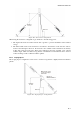
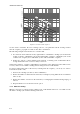
Elevation:
5 to 10 m
Radio Set
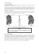
Figure B-2. Inverted V Configuration
When using the inverted V configuration, pay attention to the following points:
1. The angle between the two halves must be 90° or greater, to prevent cancellation of the radiated
energy.
2. The main radiation lobe of the inverted V is broadside to the direction of the wire, the same as
for the horizontal dipole. However, the inverted V also exhibits a minor radiation lobe directly
in line with each end of the wire. These minor radiation lobes have generally a low vertical
radiation angle, which is useful for long-distance communications. The antenna can be oriented
to take advantage of this combined radiation pattern.
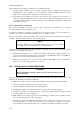
B-3.3 Sloping Dipole
The sloping dipole configuration can be used to obtain a long-distance, slightly directional radiation
pattern.
Elevation:
5 to 10 m
Radio Set
Direction of
Maximum Radiation
Make sure the + mark
is connected to upper
antenna wire
Figure B-3. Sloping Dipole Configuration