
Service Manual


MM-E 2072-09333-00
3-26
NOTE
To remove the LCD, release its four fastening screws, and then
disconnect it from the module. Also disconnect the two harnesses
connected to connectors P2 and P4 on the module.
5. If necessary, move the LCD to the replacement module.
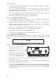
6. Orient the replacement module in accordance with Figure 3-16, and place it on the spacers.
7. Reconnect the speaker cable to the corresponding module connector.
8. Reinstall the RF shield.
LCD
Screws
Front Panel
Keypad
Inserts
Speaker
Speaker Holder
Speaker Screws
Spacers
RF Shield
Shield Screws
Gasket
CONTROL HEAD
Module
Speaker
Cable
Figure 3-16. Replacement of CONTROL HEAD Module
3-6.1.4.2 Replacement of Speaker
1. Release the 13 screws fastening the RF shield. Keep screws and washers for reuse.
2. Remove the RF shield.
3. Disconnect the speaker cable from the CONTROL HEAD module.
4. Release the screws fastening the speaker holder, and then remove the speaker. Keep the gasket
and holder for reuse.
5. Install the replacement speaker by reversing the procedure given above.