
Service Manual


MM-E 2072-09333-00
3-25
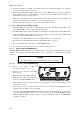
ANT Cable
Figure 3-15. Removal of HI POWER Module
3-6.1.3.2 Installing the Replacement HI POWER Module
1. Clean the remnants of heatsink compound from the body assembly and the HI POWER module.
2. Spread a thin layer of fresh compound on the bottom area of the HI POWER module.
3. Route the coaxial cable with the ANT connector over the HI POWER module as shown in
Figure 3-15.
4. Insert the HI POWER module in the corresponding slot of body assembly, slide it halfway, and
then insert the ANT connector in its hole in the rear panel.
5. Fasten the ANT connector with its nut.
6. Push the HI POWER module fully into the body assembly, and then fasten the VDC IN
connector to the rear panel with its two fasteners.
7. Fasten the HI POWER module to the body with the nine original screws.
8. Reconnect the coaxial cables between the LORD and HI POWER modules in accordance with
Figure 3-13.
9. Reconnect the flat cable between the LORD and HI POWER modules in accordance with
Figure 3-13.
10. You may close now the Micom-Z case in accordance with para. 3-6.1.1.
3-6.1.4 Replacement of Components on Front Panel Assembly
3-6.1.4.1 Replacement of CONTROL HEAD Module
Refer to Figure 3-16.
1. Release the 13 screws fastening the RF shield. Keep screws and washers for reuse.
2. Remove the RF shield.
3. Disconnect the speaker cable from the CONTROL HEAD module.
4. Remove the CONTROL HEAD module. Make sure that the keypad and the inserts remain in
their place, on the front panel.