
Service Manual


MM-E 2072-09333-00
2-40
2-6.2 CONTROL HEAD Module for Trunk-Mount Version
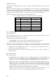
Figure 2-19 shows the functional block diagram of the CONTROL HEAD module used in the
Micom-Z trunk-mount version.
LCD
J3
Microcontroller
U1
P2
P4
Panel
Keypad Lighting
Control
Q504, Q506
LCD Heater
Control
U7, Q1, Q3, Q501
LED Lighting
Control
Q502, Q503
Voltage
Regulator
U6, Q2
13V8DC
14V7
Y1
3V
Regulator
U5
To INTERCONNECTION
3.3V
Regulator
U4
3V3
P501
3V0
Voltage
Regulator
U501
5V0
Voltage
Regulator
U502
8V0_AUDIO
Amplifier
U503
TX_AUDIO
RS-485
Line Driver
U506
PTT
RS-485
Line Receiver
U504
RS-485
Line Driver
U505
CH_RXD
CH_TXD
PTT_MIC
RX_UART0
TX_UART0
MIC_IN
Serial Control Channel (UART 0)
5V0
8V0_AUDIO
P6
Audio
Connector
Figure 2-19. CONTROL HEAD Module for Trunk-Mount Version, Functional Block Diagram
2-6.2.1 Microcontroller
Refer to Figure A-3.B, Figure A-3.C.
The microcontroller subsystem is similar to that used in the dash-mount version (para. 2-6.1.1). The
connection of the serial control channel to the LORD module (via the INTERCONNECTION module)