
Service Manual


MM-E 2072-09333-00
2-34
is inserted in the signal path by a pair of relays, controlled by the LORD module via the serial data line
SPI_DATA.
The relay control data is loaded into the serial/parallel converter U4 at the rate of the SPI_CLK clock
signal, and updates the U4 outputs when the SPI_SEL line rises to a high level. Each U4 output drives
one pair of relays, via Darlington stages in U3: at any time, only one U4 output assumes a high level,
causing the corresponding pair of relays to energize and insert a filter in the RF signal path.
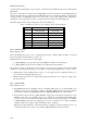
The filter ranges and the corresponding relays are listed in Table 2-8.
Table
2-8. Harmonic Filter Frequency Ranges and Controlling Relays
Filter Frequency Range Relays
1 1.6 to 2.43 MHz K101, K102
2 2.43 to 3.7 MHz K201, K202
3 3.7 to 5.6 MHz K301, K302
4 5.6 to 8.5 MHz K401, K402
5 8.5 to 13 MHz K501, K502
6 13 to 19.8 MHz K601, K602
7 19.8 to 30 MHz K701, K702
2-5.4 Power Sensor
Refer to Figure A-2.C.
The forward/reflected power sensor, comprising T4 and the rectifiers CR6 and CR7, is inserted
between the filters and the antenna connector, J2.
During transmission, it generates two DC signals:
a. V_FWD_RADIO, proportional to the forward RF power delivered to the antenna
b. V_REV_RADIO, proportional to the RF power reflected from the antenna.
The signals are sent to both the ALC control circuits, and to the microcomputer system in the LORD
module, for controlling the transmit power as a function of the following parameters (see para. 2-5.5):
• VSWR value: if the VSWR increases above 2:1, the output power is gradually decreased, to
protect the radio from high reflected power.
• Harmonic filter insertion losses: if the harmonic filter insertion loss is too high, the output power
level is decreased.
2-5.5 ALC Circuits
Refer to Figure A-2.E.
a. Internal/External Power Amplifier Selector. Normally, Micom-Z uses its internal RF power
amplifier, and a low level is applied to Q807 via the EXT_AMP_EN line. The analog switches
in U12 then connect the V_FWD_RADIO and V_REV_RADIO lines to the ALC circuits.
b. Forward Power Control. The V_FWD_RADIO voltage passes through the peak detector (U5,
CR809) to the ALC error amplifier, U13. U13 compares the level with the ALC_REF_DAC
power reference received from the LORD module via the non-inverting buffer U15: a higher
V_FWD_RADIO level causes the output (pin 4) of U13 to assume a lower voltage, resulting in
a higher voltage at the emitter of Q23, which drives the V_ALC line.
This increases the attenuation of the ALC attenuator, tending to return the transmit power to its
normal level. The reverse action occurs when V_FWD_RADIO is less than normal.