
Service Manual


MM-E 2072-09333-00
2-17
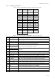
2-3. CONNECTOR DATA
2-3.1 Micom-Z Connector Data
Table
2-3. Micom-Z Microphone Connector, Pin Functions
Pin Designation Description
1 SWA+ Power output to the microphone
2 RXD Serial communication line (input)
3 TXD Serial communication line (output)
4 GND Ground line
5 MIC AUDIO
Input audio signals generated by the microphone (600 Ω
impedance; 300 mV tone is required for full output power).
6 PTT MIC Activates transmission by short to ground.
7 MONITOR Mutes the speaker before transmission is enabled (short
momentary to ground to open speaker).
8 AUDIO OUT
Receive audio output to earphone (600 Ω, 300 mVRMS)
Table
2-4. ACCESSORY Connector Pin Functions
Pin Designation Description
1 SPKR-
Differential output to external 8Ω, 5W speaker
2 STOP SCAN Digital control input for stop scan function (optional function)
3 SPKR+
Differential output to external 8Ω, 5W speaker
4 EXT RX AUDIO+
5 EXT RX AUDIO-
Differential received audio output (0 dBm/600Ω; not controlled by
volume)
6 EXT TX AUDIO+
7 EXT TX AUDIO-
Differential transmit audio input (600Ω input impedance, 0 dBm is
required for full power)
8 PTT IN VOICE Transmission command (short to ground) for voice signals
9 PTT IN DATA Transmission command (short to ground) for data signals
10
PTT IN CW Transmission command (short to ground) for CW (Morse) signals
11
SW A+ Primary DC voltage current limited output (max 1A)
12
DSI/KW CC
BDM – Data serial in/optional external amplifier channel change
13
KW ON/OFF Optional external amplifier power on/off output
14
REV CLOSE LOOP Close the radio ALC loop (input from optional external amplifier)
15 RXA Receive input (point-to-point protocol to host/HLC)
16
TXA Transmit output (point-to-point protocol to host/HLC)
17
EX RESET External RESET input (for BDM)
18
GND Ground
19
KW PTT PTT output to optional external amplifier (active low)
20
EXT ALARM External alarm output (open collector, pulled to ground when external
alarm is activated)
21 VPP Flash programming voltage, input to BDM