
Service Manual


MM-E 2072-09333-00
2-15
2-1.3 Micom-Z Cooling Tray
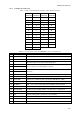
Figure 2-11 shows the structure of the Micom-Z cooling tray.
The cooling tray includes one module, the FAN CONTROL module, which provides point-to-point
connections between the two 25-pin connectors of the cooling tray. The module also includes the fan
control circuit, which enables to turn the supply voltage to the fan ON or OFF in accordance with the
control signal provided by the Micom-Z installed on the tray.
The connections between the radio side connector, the front panel jacks, and the fan are made by a
harness, which connects to the 9-pin D-type connector on the module.
Internal
Fan Cable
FAN CONTROL
Module
Cooling
Fan
Figure 2-11. Micom-Z Cooling Tray Structure