
Service Manual


MM-E 2072-09333-00
2-3
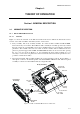
c. CONTROL HEAD module, includes the following main circuits:
(1) Microcomputer subsystem, built around a microcontroller, used to manage the operator
interface, transfers the operator commands to the main microcomputer subsystem located
on the LORD module, and controls the LCD and its operational conditions.
(2) Serial RS-232 port for communication with the Micom-Z management subsystem.
(3) Audio subsystem, including the microphone amplifier, the audio power amplifier for the
internal speaker, and the volume control/ON-OFF switch.
2-1.1.3 Functional Block Diagram
The functional block diagram of Micom-Z dash-mount version is shown in Figure 2-3.
2-1.1.3.1 Transmit Path
a. Selection of Signal Source. The transmit path can receive modulation signals from a
microphone connected to the front panel audio connector or signals from equipment connected
to the rear panel ACCESSORY connector (audio from an accessory device, a modem, or
telegraphy). Each source provides a different PTT signal, and therefore the selection of the
signal to be transmitted is made in accordance with the active PTT signal:
• MIC PTT – PTT from the microphone connected to the front panel connector, transmits the
voice signal provided by the microphone.
• Voice PTT – PTT from an accessory connected to Micom-Z through the ACCESSORY
connector, transmits the voice signal from the accessory device.
• Data PTT – PTT from a data device, for example, a modem, connected to Micom-Z through
the ACCESSORY connector, causes Micom-Z to switch to the data mode and transmit the
modem signal.
• CW PTT – PTT from a Morse key connected to Micom-Z through the ACCESSORY
connector, causes the radio to switch to the CW (Morse) transmission mode.
In parallel, the radio operating mode is automatically adapted for best performance with the
signal expected for the detected PTT type.
b. Processing of Transmit Signal. The selected audio modulation signal is converted to a digital
data stream by the A/D converter section of a codec, for processing by the DSP subsystem. The
DSP outputs a digital representation of the signal, in accordance with the modulation mode
selected by the operator (LSB, USB, AME or PILOT). This digital representation is converted
to the actual IF modulated signal, on a carrier frequency of 1.05 MHz, by a digital sideband
modulator (DSM).
c. ISB Option. When the ISB option is installed, the master sideband signal is processed as
explained above. In addition, the transmit signal received through the TX_AUDIO_ISB line of
the ACCESSORY connector is converted to a digital data stream by an additional codec. The
codec supplies the data stream to the DSP, which processes the signal in parallel with the other
(master sideband) data stream, and generates the representation of an ISB signal for the DSM.
d. Generation of RF Transmit Signal.
(1) The 1.05 MHz transmit IF signal generated by the DSM is converted by the second mixer
to 45.1 MHz, by mixing it with a 46.15 MHz local oscillator signal provided by
synthesizer 2 (para. 2-1.1.3.3).
The 45.1 MHz is filtered and amplified by the first IF processor.
(2) The 45.1 MHz IF transmit signal is down-converted to the desired RF frequency by the
first mixer. The conversion is performed by mixing the IF signal with the variable local
oscillator signal provided by synthesizer 1 (para. 2-1.1.3.3).
The resulting low-level RF signal is amplified by the exciter amplifier, and supplied to
the RF power amplifier in the HI POWER module.