
Installation guide


Installing the StormPort 600 Modem 1-15
Revision 1.00 StormPort 600 Modem Installation Guide 08-01143-01
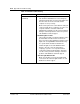
Task:
Installing the Modem
Note: Some PCs and laptops require an adapter between the RJ-45
Ethernet cable and the Ethernet connector on the PC/laptop (the
adapter is often a round, 8-pin connector).
Step Action
1 Make sure that all of the StormPort 600 Modem equipment is available before
proceeding.
2 Connect the RJ-45 Ethernet cable to the 10Base-T Ethernet Card connector
on the rear of the computer. Connect the other end of cable to the Ethernet
port on the rear of the modem labeled: To PC.
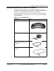
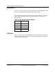
3 The telephone is connected with an RJ-11 modular phone line cord to a
telephone wall jack. Disconnect the telephone line cord from the telephone
wall jack and insert it into the jack in the rear of the modem identified with this
icon:
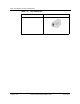
4 Connect the RJ-11 modular phone cord to the connector on the rear of the
modem labeled, To Wall Jack. This connector is identified with a telephone
line symbol.
5 Insert the other end of the phone cord into the telephone wall jack.
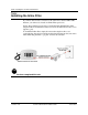
6 Con nect the rounded plug end of the power supply cord into the 5V AC
connector on the rear of the modem.
7 Plug the power supply into wall outlet. This completes the modem physical
installation. At this point, the Power and the Loop Status indicator lights
should be green.
Note:
See “Dip Switches” on page 1-16 for more information on the
StormPort 600 modem LED indicators.
STOP
You have completed this task.