
User guide


CG2-SHANTY • CompactPCI GPS Receiver/Clock
- 18 -
EKF Elektronik GmbH • Philipp-Reis-Str. 4 • 59065 HAMM • Germany
Tel. +49 (0)2381/6890-0 • Fax. +49 (0)2381/6890-90 • E-Mail info@ekf.de • Internet www.ekf.com
Technical Reference
GPS Receiver Module
General Features
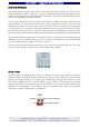
The CG2-SHANTY is equipped with the Navman Jupiter GPS receiver module, a 12 parallel
channel receiver engine. Each of these receivers continuously tracks all satellites in view and
provides accurate satellite positioning data. The Jupiter module size is about 28 square
centimeters and satisfies harsh industrial requirements. The Jupiter module decodes and
processes signals from all visible GPS satellites. These satellites, in various orbits around the
Earth, broadcast radio frequency (RF) ranging codes and navigation data messages. The Jupiter
receiver uses all available signals to produce a highly accurate and robust navigation solution.
The 12-channel architecture provides rapid Time-To-First-Fix (TTFF) under all startup conditions.
While the best TTFF performance is achieved when time of day and current position estimates
are provided to the receiver, the flexible SiRF signal acquisition system takes advantage of all
available information to provide a rapid TTFF. Acquisition is guaranteed under all initialization
conditions as long as visible satellites are not obscured. To minimize TTFF following a power
down, the Jupiter receiver is sourced by a Lithium Cell on the CG2-SHANTY board to maintain
power to the Static Random-Access Memory (SRAM) and Real-Time Clock (RTC) for periods
following the loss of prime power. The use of the battery voltage assures the shortest possible
TTFF following a short power down. The Jupiter receiver supports two dimensional (2-D)
operation when less than four satellites are available or when required by operating conditions.
Altitude information required for 2-D operation is determined by the receiver.
The Jupiter module contains two independent serial ports, one of which is configured for
primary input and output data flow using the National Marine Electronics Association (NMEA-
0183) format. The second port is used to receive Differential GPS (DGPS) corrections in the Radio
Technical Commission For Maritime Services (RTCM SC-104) format. The Jupiter receiver
supports DGPS operations for dramatically improved accuracies over standard GPS (while
Selective Availability is activated by US government). The primary I/O port of the Jupiter (NMEA)
is connected to the first port of the UART controller, while the secondary port (RTCM) ist
connected to both the front panel connector SP2 and the second port of the UART controller of
the CG2-SHANTY (see block diagram CG2-SHANTY).
For applications that require timing synchronization to GPS accuracies, the Jupiter receiver
provides an output timing pulse that is synchronized to one second Universal Time Coordinated
(UTC) boundaries. This timing pulse is available by an two single row headers JUTC1 and JUTC3
on the CG2-SHANTY board. This timing signal could generate a timing interrupt on the UART
controller therefore JUTC1 should be set. Its also possible to use this timing signal to generate
a timing interrupt directly on the INTP of the CompactPCI bus (J1 d4). The CompactPCI CPU
boards CC9-SAMBA and CD2-BEBOP are already capable of handling this interrupt. This timing
pulse is also used to drive an indicator LED visible from the CG2-SHANTY boards front panel.