ENGLISH
SAFETY SYMBOLS This manual uses the safety symbols below. They denote critical information. Please read them carefully. WARNING Failure to abide by the information in a WARNING may result in serious injury and can be life threatening. CAUTION Failure to abide by the information in a CAUTION may result in moderate injury and/or property or product damage. Indicates a prohibited action. Indicates to ground for safety. Copyright© 2001 by EIZO NANAO CORPORATION. All rights reserved.
TABLE OF CONTENTS PRECAUTIONS .............................................................................. 4 1. INTRODUCTION ............................................................................ 9 2. ENGLISH 1-1. Features ....................................................................................................... 9 1-2. Package Contents ........................................................................................ 9 1-3. Controls & Connectors ...............................
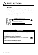
PRECAUTIONS IMPORTANT! ´ This product has been adjusted specifically for use in the region to which it was originally shipped. If operated outside the region to which it was originally shipped, the product may not perform as stated in the specifications. ´ To ensure personal safety and proper maintenance. Please read this section and the caution statements on the unit (refer to the figure below). [Location of the Caution Statements] CAUTION:Risk of electric shock. Do not open.
WARNING ´ Place the unit on a strong, stable surface. A unit placed on an inadequate surface may fall, resulting in injury or equipment damage. If the unit falls, disconnect the power immediately and have the unit checked by a qualified service engineer before using it again. Using a unit after it has been dropped may result in fire or electric shock. ENGLISH • Keep small objects or liquids away from the unit.
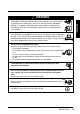
WARNING ´ Use the correct voltage. * The unit is designed for use with a specific voltage only. Connection to another voltage than specified in this User’s Manual may cause fire, electric shock, or other damage. * Do not overload your power circuit, as this may result in fire or electric shock. * For proper connections of the power cord, be certain to plug the power cord to the provided unit connector and directly to a wall outlet. Not doing so may result in fire or electric shock.
CAUTION WARNING ENGLISH ´ Handle with care when carrying the unit. Disconnect the power cord and cables when moving the unit. Moving the unit with the cord attached is dangerous. It may result in injury or equipment damage. * When handling the unit, grip the bottom of the unit firmly with both hands ensuring the panel faces outward before lifting. OK Dropping the unit may result in injury or equipment damage. ´ Do not block the ventilation slots on the cabinet.
Suggestions for Maximizing Comfort ´ To lessen the chance of possible injury and to increase your comfort and productivity while you operate the unit, we suggest the followings: * Avoid less favorable body positioning. Sit back on the chair with your back straight. * Adjust the height of the chair so that the both soles touch the floor. * Adjust the height of your chair, unit, or keyboard so that you can keep your wrists straight while typing. * Set the unit slightly below eye level.
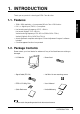
1. INTRODUCTION Thank you very much for choosing an EIZO Color Monitor. 1-1. Features ENGLISH • 1280 x 1024 resolution p.36) incorporated 16 inch Color LCD Monitor • DVI p.35) digital input (TMDS p.36)) compliant • Horizontal scanning frequency of 31.5 ~ 80kHz Horizontal (Digital): 31.
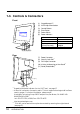
1-3.
2. CABLE CONNECTION 2-1. Before connecting Before connecting your monitor to the PC, change the display screen settings (resolution and frequency) in accordance with the charts below. Resolution 640 x 480 640 x 480 720 x 400 800 x 600 832 x 624 1024 x 768 1152 x 864 1152 x 870 1280 x 960 1280 x 1024 Frequency ~ 85 Hz 66.
2-2. Connecting the signal cable • Be sure that the power switches of both the PC and the monitor are OFF. 1. Plug the signal cable into the DVI-I connector at the rear of the monitor and the other end of the cable into the video connector on the PC. After connecting, secure the connection with the screw-in fasteners.
2. Plug the power cord into the power connector on the rear of the monitor and plug the other end of the power cord into a power outlet. ENGLISH WARNING WARNING • Use the enclosed power cord and connect to the standard power outlet of your country. Be sure to remain within the rated voltage of the power cord. Not doing so may cause in fire or electric shock. • The equipment must be connected to a grounded main outlet. Not doing so may cause in fire or electric shock. 3.
3. ScreenManager 3-1. How to use the ScreenManager As shown on the display, the ScreenManager is used to adjust the LCD monitor. ScreenManager consists of main menus and sub menus. Adjustments are made using the Enter and Control buttons (up, down, right and left) located on the front panel. Control Buttons Enter Button Auto Adjustment Button 1. Entering the ScreenManager Push the Enter Button once to display the main menu of the ScreenManager. [ Main Menu ] 2.
3-2. ScreenManager Adjustments and Settings. The following table shows all the ScreenManager’s adjustment and setting menus. “*” indicates adjustments of analog input only and “**” indicates digital input only.
3-3. Useful Functions Adjustment Lock Use the “Adjustment Lock” function to prevent any accidental changes. Locked function Unlocked function • Auto adjustment button adjustments and settings in the ScreenManager. • Adjustment of contrast and brightness by the control buttons. • To lock Press on the Auto adjustment button while switching on the monitor’s power switch on the front panel.
Off Timer [Procedure] (1) Select “Off Timer” in the ScreenManager “Others” menu. (2) Select “Enable” and press the right and left buttons to adjust the “On Period” (1 to 23 hours). [Off timer system] PC Monitor LED On Period (1H~23H) Operation Green Last 15 min. in "On period" Advance Notice *1 Green Flashing "On period" expired "Power Off" Mode Flashing yellow slowly *1 Advance notice (LED flashing green) will be given 15 minutes before the monitor automatically enters the “Power Off” mode.
4. ADJUSTMENT 4-1. Screen Adjustment • Allow the LCD monitor to stabilize for at least 20 minutes before making image adjustments. Screen adjustments for the LCD monitor should be used in suppressing screen flickering and also for adjusting the screen to its proper position. There is only one correct position for each display mode. When using the analog input, it is also recommended to use the ScreenManager function when first installing the display or whenever changing the system.
3. Adjust by using “Screen” menu in the ScreenManager. (1) Vertical bars appear on the screen. Æ Use the “Clock” p.35) adjustment • When adjusting the “Clock,” the horizontal screen size will also change. (2) Horizontal flickering, blurring or bars appear on the screen. Æ Use the “Phase” p.36) adjustment. Select the “Phase” and eliminate the horizontal flickering, blurring or bars by using the right and left buttons. • Horizontal bars may not completely disappear from the screen depending on the PC. 4.
(3) The screen position is incorrect. Æ Use the “Position” adjustment. The correct displayed position of LCD monitor is decided because the number and the position of the pixels are fixed. The “Position” adjustment moves the image to the correct position. Select “Position” and adjust the position so all the dotted line appear around screen, by using the up, down, right and left buttons. (4) Screen image is smaller or larger than the actual screen images. Æ Use the “Resolution” adjustment.
4. To set the Output signal range (Dynamic Range) of the signal. Æ Use the “Range Adjustment”.p.36) [Auto] Push the Auto adjustment button on the front panel while displaying the “Range adjustment” menu to automatically adjust the range. The screen blanks for a moment, and adjusts the color range to display the whole color gradation of the current output signal.
4-2. Displaying the low resolutions The lower resolutions are enlarged to full screen automatically. Using the “ScreenSize” function in the “Others” menu enables to change the screen size. 1. To enlarge the screen size when displaying a low resolution. Æ Select “Screen Size” Select the “Screen Size” in the others menu and select the screen size by using the up and down buttons. • Full • Enlarged • Normal Displays the picture on the screen in full, irrespective of the picture’s resolution.
2. To be clear-cut the letters or lines of the enlarged screen. Æ Switch the “Smoothing” setting. • “Smoothing” is disabled in the following cases. * 1280 x 1024 of resolution * “Enlarged” mode in “Screen Size” setting with the 1280 of the horizontal resolution (i.e. 1280 x 960) * “Normal” mode in the “Screen Size” setting 3. To set the brightness of the black area surrounding the image. Æ Set the “Border Intensity” In the “Normal” mode, the outer area (border) is usually black.
4-3. Color Adjustment The “ColorManagement”menu in the ScreenManager enables to change the color of the screen. Before the Color adjustment • Allow the LCD monitor to stabilize for at least 20 minutes before making color adjustments. • After finishing each adjustment in the custom mode, select “Save” icon to resister the adjustment. Otherwise, the adjustment will be lost. • The adjustment values represent the current level within the specific adjustment only. They are available only as a reference tool.
2. To change the saturation. Æ Use the “Saturation” adjustment. • The “Saturation” adjustment may cause undisplayable color tone. 3. To change the flesh color, etc. Æ Use the “Hue” adjustment. The “Hue” can be selected from -16 to 16. To register the adjustment, select the “Save” icon and then push the enter button. • The “Hue” adjustment may cause undisplayable color tone. 4. To adjust each color (red, green and blue). Æ Use the “Gain”p.35) adjustment.
4-4. Power-save Setup • Do your part to conserve energy, turn off the monitor when you are finished using it. Disconnecting the monitor from the power supply is recommended to save energy completely. Analog Input This monitor complies with the VESA DPMS p.36) standard. 1. 2. Set the PC’s power saving settings. Select “VESA DPMS” in the “PowerManager” menu.
5. ATTACHING AN ARM STAND The L461 can be used with an arm stand by removing the tilt stand and attaching the arm stand to the terminal. ENGLISH ´ Use an arm stand that satisfies the followings. • When using the L461 with an arm stand, the arm stand must be VESA approved : * Use an arm stand with a 75 mm x 75 mm hole spacing on the arm mounting pad. * Use an arm stand that is able to support an object weighting 8.0 kg. ´ TÜV/GS approved arm stand.
3. Attach an arm stand to the L461 securely. WARNING WARNING ´ When attaching an arm stand, please refer to the user’s manual of the arm stand and install the unit securely with the enclosed screws. Not doing so may cause the unit to come unattached, which may result in injury or equipment damage. When the unit is dropped, please ask your dealer for advice. Do not continue using a damaged monitor. Using a damaged monitor may result in fire or electric shock.
6. TROUBLESHOOTING Problems 1. No picture • Indicator status: Off • Indicator status: Green • Indicator status: Yellow • Indicator status: Slowly flashing Yellow 2. Following messages appear. (Error messages will remain on the screen for 40 seconds.) •Whenever an error signal message appears, the signal frequency will be displayed in red. (Example) Points to check with possible solutions Check that the power cord is correctly connected.
Problems Points to check with possible solutions 3. Display position is incorrect. Adjust the image position using the “Position”. (p.20) If the problem persists, use the graphics board’s utility software to change the display position if available. 4. Screen image is smaller or larger than the actual screen images. Adjust the resolution using the “Resolution”. (p.20) 5. Vertical bars of distortion appear. Decrease the vertical bars using the “Clock”. (p.19) 6. Horizontal bars of distortion appear.
Problems Points to check with possible solutions Leaving the screen white may solve the problem. 12. The “Smoothing” can not be selected. “Smoothing” is disabled in the following cases. • 1280 x 1024 of resolution • “Enlarged” mode in the “Screen Size” setting with the 1280 of horizontal resolution (i.e. 1280 x 960) • “Normal” mode in the “Screen Size” setting. 13. The utility disk is unable to be opened (for Macintosh only).
7. CLEANING Periodic cleaning is recommended to keep the monitor looking new and to prolong its operation lifetime. • Never use thinner, benzene, alcohol (ethanol, methanol, or isopropyl alcohol), abrasive cleaners, or other strong solvents, as these may cause damage to the cabinet or LCD panel. Cabinet To remove stains, wipe the cabinet with a soft, lightly moistened cloth using a mild detergent. Do not spray wax or cleaner directly onto the cabinet.
8. SPECIFICATIONS LCD Panel Dot Pitch Scan Frequency Resolution Dot Clock (Max) Display Colors Display Area Power Supply Power Consumption Input Connector Input Signal Analog Digital Signal registration Plug & Play Dimensions Dimensions (without stand) Weight Weight(without stand) Temperature Humidity 1280 dots x 1024 lines 135 MHz 108 MHz(Digital) 16 milion colors (max) 317.4 mm (H) x 253.9 mm (V) (12.5” (H) x 10.0” (V)) (Viewable image size: 406 mm (16.0”)) 100-120/200-240 VAC±10%, 50/60 Hz, 0.7 A/0.
Dimensions 384 (15.1) 319.2 (12.6) 25° 3° 62.2(2.4) 172.8(6.8) 255.8(10.1) 325(12.8) 387.2(15.2) 36.8(1.4) 69(2.7) 167.5(6.6) 171.4(6.7) FRONT SIDE Default Settings Default Settings are as follows: ScreenManager menu Default Settings Contrast 100% Brightness 100% Smoothing On Color Mode Standard Temperature Off PowerManager VESA DPMS DVI DMPM(Digital Input) Screen Size Full Screen Off Timer Disable Menu Off Timer 45 seconds Language English 34 8. SPECIFICATIONS 170(6.
9. GLOSSARY Afterimage The Afterimage is particular to LCD monitors when the monitor screen is left on for a long period without use. The “Afterimage” can be removed gradually by changing the displayed image. With the analog input signal display, the analog signal is converted to a digital signal by the LCD circuitry. To convert the signal correctly, the LCD monitor needs to produce the same number clock pulse as the dot clock of the graphics system.
Phase The phase adjustment decides the sampling timing point for converting the analog input signal to a digital signal. Adjusting the phase after the clock adjustment will produce a clear screen. Range Adjustment The Range Adjustment controls the level of output signal range to display the whole color gradation. Resolution The LCD panel consists of a fixed number of pixel elements which are illuminated to form the screen image. The EIZO L461 consists of 1280 horizontal pixels and 1024 vertical pixels.
10.
MEMO 38 10.
APPENDIX / ANHANG / ANNEXE Pin Assignment Pin-Belegung Affectation des Broches * DVI-I Connector 1 2 3 4 5 6 7 Pin No. 8 C1 C2 C3 C4 C5 1 Signal TMDS Data2- 9 10 11 12 13 14 15 16 17 18 19 20 21 22 23 24 2 Pin No. TMDS Data1/3 11 21 Shield TMDS Data2+ 12 TMDS Data2/4 3 13 Shield 4 NC* 14 5 NC Pin No.
Mode ii APPENDIX Dot Clock Frequencies A: Front Porch B: Sync Period H µs/ Dot V ms/ Line H µs/ Dot V ms/ Line MHz H kHz V Hz VGA 640 x 480 25.175 31.468 59.941 0.636/ 16 0.318/ 10 3.813/ 96 0.054/ 2 VGA 720 x 400 28.322 31.468 70.087 0.636/ 18 0.381/ 12 3.813/ 108 0.064/ 2 Macintosh 640 x 480 30.24 35.00 66.67 2.116/ 64 0.086/ 3 2.116/ 64 0.086/ 3 Macintosh 832 x 624 57.28 49.73 74.55 0.559/ 32 0.020/ 1 1.117/ 64 0.060/ 3 Macintosh 1152 x 870 100.0 68.68 75.
C: Back Porch D: Blanking Period E:Display Period F:Total Cycle V ms/ Line H µs/ Dot V ms/ Line H µs/ Dot V ms/ Line H µs/ Dot V ms/ Line 1.907/ 48 1.048/ 33 6.356/ 160 1.430/ 45 25.442/ 640 15.254/ 480 31.778/ 800 16.683/ 525 1.907/ 54 1.111/ 35 6.356/ 180 1.556/ 49 25.422/ 720 12.712/ 400 31.778/ 900 14.267/ 449 3.175/ 96 1.114/ 39 7.407/ 224 1.286/ 45 21.164/ 640 13.714/ 480 28.571/ 864 15.000/ 525 3.911/ 224 0.784/ 39 5.586/ 320 0.865/ 43 14.524/ 832 12.
MEMO iv APPENDIX
[Applicable to gray (standard color version only).] Congratulations! You have just purchased a TCO’99 approved and labelled product! Your choice has provided you with a product developed for professional use. Your purchase has also contributed to reducing the burden on the environment and also to the further development of environmentally adapted electronics products.
[Applicable to gray (standard color version only).] Environmental requirements Flame retardants Flame retardants are present in printed circuit boards, cables, wires, casings and housings. Their purpose is to prevent, or at least to delay the spread of fire. Up to 30% of the plastic in a computer casing can consist of flame retardant substances. Most flame retardants contain bromine or chloride, and those flame retardants are chemically related to another group of environmental toxins, PCBs.
For U.S.A, Canada, etc. (rated 100-120 Vac) Only FCC Declaration of Conformity We, the Responsible Party EIZO NANAO TECHNOLOGIES INC. 5710 Warland Drive, Cypress, CA 90630 Phone: 562 431 5011 declare that the product Trade name: EIZO Model: FlexScan L461 is in conformity with Part 15 of the FCC Rules.