
User Manual

Welcome Page 23 of 54
file://C:\TEMP\~hhA856.htm 8/12/02
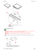
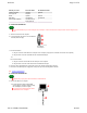
c. IMPORTANT: Examine the leg assemblies: one side of each assembly has 10 holes (2 groups of 5) and the other side has 8 holes (2
groups of 4). In this step, the sides with 10 holes must face away from the crossbars.
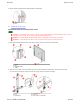
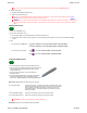
Attach both crossbars to one leg assembly using eight screws as shown below. The screws pass through the 4 outermost holes in
each group of 5 holes. Attach the other leg assembly to the crossbars in the same way.
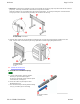
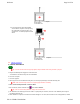
d. Thread two Knob Screws into each leg through the mounting bracket. The lower Know Screw should go toward the rear of the
stand. Screw the Knob Screws all the way into the leg. Adjust tablet to desired height by lifting tablet from front.
Next: Assemble the electronic pens.
3. Assemble the SchoolBoard pen(s)
A Crossbar
B Screw, 1/4-20 x 2" flat head
C Leg assembly
A Knob Screw (4)
B Mounting bracket
C Slot
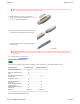
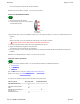
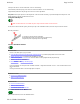
a. Locate the marker holders, electronics modules,
batteries, pen caps and markers supplied.
The pens are electronically coded to match the plastic
colors: black, blue, red and green.
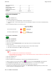
b. Remove the marker's cap and replace it with a
MeetingBoard pen cap.
c. Insert a marker into the pen housing with the matching
color (e.g., red marker goes in red housing)
A Marker holder
B Electronics module
C Marker
D Pen cap