
User Manual

GB
- 17 -
5.2 Fitting and adjusting the depth stop
(Fig. 3/Item 7)
The depth stop (7) is held in place by the additi-
onal handle (6) by clamping. The clamp can be
released and tightened by turning the handle.
•
Release the clamp and fit the depth stop (7)
in the recess provided for it in the additional
handle.
•
Set the depth stop (7) to the same level as
the drill bit.
•
Pull the depth stop back by the required dril-
ling depth.
•
Turn the handle on the additional handle (6)
until it is secure.
•
Now drill the hole until the depth stop (7) tou-
ches the workpiece.
5.3. Tool insertion (Fig. 4)
•
Clean the tool before insertion and apply a
thin coating of drill bit grease to the shaft of
the tool.
•
Pull back and hold the locking sleeve (2).
•
Insert the dust-free tool into the tool mounting
as far as it will go whilst turning it. The tool will
lock itself.
•
Check that it is properly secure by pulling the
tool.
5.4 Tool removal (Fig. 5)
Pull back and hold the locking sleeve (2) and re-
move the tool.
6. Operation
Danger
To prevent all danger, the machine must only be
held using the two handles (6/8). Otherwise there
may be a risk of suff ering an electric shock if you
drill into cables.
6.1 ON/OFF switch (Fig. 6/Item 4)
•
First fit a suitable drill bit into the tool (see
5.3).
•
Connect the mains plug to a suitable socket.
•
Position the drill in the position you wish to
drill.
To switch on:
Press the ON/OFF switch (4)
Continuous operation:
Secure the ON/OFF switch (4) with the locking
button (5).
To switch off :
Press the ON/OFF switch (4) briefl y.
6.2 Adjusting the speed (Fig. 6/Item 4)
•
You can infinitely vary the speed whilst using
the tool.
•
Select the speed by applying a greater or les-
ser pressure to the ON/OFF switch (4).
•
Select the correct speed: The most suitable
speed depends on the workpiece, the type of
use and the drill bit used.
•
Low pressure on the ON/OFF switch (4): Lo-
wer speed
•
Greater pressure on the ON/OFF switch (4):
Higher speed
•
Tip: Start drilling holes at low speed. Then
increase the speed in stages.
Benefi ts:
•
The drill bit is easier to control when starting
the hole and will not slide away.
•
You avoid drilling messy holes (for example in
tiles).
6.3 Preselecting the speed (Fig. 6/Item 9)
•
The speed setting ring (9) enables you to
define the maximum speed. The ON/OFF
switch (4) can only be pressed to the defined
maximum speed setting.
•
Set the speed using the setting ring (9) on the
ON/OFF switch (4).
•
Do not attempt to make this setting whilst the
drill is in use.
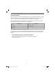
6.4 Clockwise/Counter-clockwise switch
(Fig. 6/Item 10)
•
Change switch position only when the drill is
at a standstill!
•
Switch the direction of the hammer drill using
the clockwise/counter-clockwise switch (10):
Direction Switch position
Clockwise
(forwards and drill) Pushed in to the right
Counter-clockwise
(reverse) Pushed in to the left
Anl_TC_RH_800_E_SPK1.indb 17Anl_TC_RH_800_E_SPK1.indb 17 08.10.15 08:0708.10.15 08:07