
Operating instructions


Retighten the fixing screw (30) and mount the
table insert (6) (Fig. 8.4).
Remount the blade guard (2) (see 8.3).
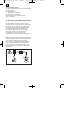
7.6 Fitting/changing the blade (Fig. 21)
Important. Pull out the power plug and wear
protective gloves.
Dismantle the saw blade guard (2) (see 8.3).
Remove the table insert (6) by undoing the two
countersunk head screws (see 8.4).
Undo the nut with a wrench (size 24) on the nut
itself and a second fork wrench (size 10) on the
motor shaft to apply counter-pressure.
Important. Turn the nut in the direction of
rotation of the saw blade.
Take off the outer flange and pull the old saw
blade off the inner flange by dropping the blade at
an angle.
Clean the saw blade flange thoroughly with a wire
brush before fitting the new saw blade.
Mount and fasten the new saw blade in reverse
order.
Important. Note the running direction. The
cutting angle of the teeth must point in
running direction, i.e. forwards (see the
arrow on the blade guard).
Refit and set the table insert (6) and the saw
blade guard (2) (see 8.3, 8.4)
Check to make sure that all safety devices are
properly mounted and in good working condition
before you begin working with the saw again.
8. Operation
8.1. ON/OFF switch (Fig. 22/Item 11)
To turn the saw on, press the green button “I” .
Wait for the blade to reach its maximum speed of
rotation before commencing with the cut.
To turn the equipment off again, press the red
button “0”.
8.2. Cutting depth (Fig. 22).
Turn the hand wheel (8) to set the blade (5) to the
required cutting depth.
Turn anti-clockwise:
larger cutting depth
Turn clockwise:
smaller cutting depth
8.3. Setting the angle (Fig. 22)
Undo the fixing handle (9).
Turn the handle to set the desired angle on the
scale.
Lock the fixing handle again in the required angle
position.
8.4 Parallel stop
8.4.1. Stop height (Fig. 23-26)
The stop rail (e) for the parallel stop (7) has two
different guide faces (high and low).
For thick material you must use the stop rail (e) as
shown in Fig. 25, for thin material (with a
workpiece thickness of less than 25 mm) you
must use the stop rail as shown in Fig. 26.
8.4.2 Turning the stop rail (Fig. 23-26)
First undo the wing nuts (f) to turn the stop rail (e).
The stop rail (e) can now by pulled off the guide
rail (h) and can be pushed back over it with the
appropriate guide.
Retighten the wing nuts (f).
8.4.3 Cutting width (Fig. 26-28)
The parallel stop (7) has to be used when making
longitudinal cuts in wooden workpieces.
The parallel stop should be mounted on the right-
hand side of the saw blade (5).
Place the parallel stop on the guide rail for the
parallel stop (12) from above (Fig. 26).
There are 2 scales (j/k) on the guide rail for the
parallel stop (12) which show the distance
between the stop rail (e) and the saw blade (5)
(Fig. 27).
Depending on this, choose the appropriate scale
to suit whether the stop rail (e) is turned for thick
or thin material:
High stop rail (thick material):
Scale j
Low stop rail (thin material):
Scale k
Set the parallel stop (7) for the required
dimension using the inspection window (I) and
secure it using the eccentric lever for the parallel
stop (31).
8.4.4 Adjusting the stop length (Fig. 29)
The stop rail (e) can be moved in longitudinal
direction in order to prevent the workpiece from
becoming jammed.
Rule of thumb: The rear end of the stop comes up
against an imaginary line that begins roughly at
29
GB
Anleitung_RT_TS_1725_1_U_SPK1:_ 28.10.2011 8:45 Uhr Seite 29