MULTIMEDIA PROJECTOR MODEL LC-XT4U/E ✽ Projection lens is optional. OWNER'S INSTRUCTION MANUAL Downloaded From projector-manual.
TO THE OWNER Before operating this projector, read this manual thoroughly and operate the projector properly. This projector provides many convenient features and functions. Operating the projector properly enables you to manage those features and maintain it in better condition for a considerable time. Improper operation may result in not only shortening the product life, but also malfunctions, fire hazard, or other accidents.
SAFETY INSTRUCTIONS All the safety and operating instructions should be read before the product is operated. Read all of the instructions given here and retain them for later use. Unplug this projector from AC power supply before cleaning. Do not use liquid or aerosol cleaners. Use a damp cloth for cleaning. This projector should be operated only from the type of power source indicated on the marking label.
COMPLIANCES Federal Communication Commission Notice This equipment has been tested and found to comply with the limits for a Class A digital device, pursuant to Part 15 of FCC Rules. These limits are designed to provide reasonable protection against harmful interference when the equipment is operated in a commercial environment.
TABLE OF CONTENTS FEATURES AND DESIGN PREPARATION NAME OF EACH PART OF PROJECTOR SETTING-UP PROJECTOR CONNECTING AC POWER CORD LENS INSTALLATION POSITIONING PROJECTOR LENS SHIFT ADJUSTMENT PICTURE LEVEL AND TILT ADJUSTMENT INSTALLING PROJECTOR IN PROPER POSITION MOVING PROJECTOR 6 7 7 8 8 9 9 9 10 10 11 CONNECTING PROJECTOR 12 TERMINALS OF PROJECTOR CONNECTING TO COMPUTER CONNECTING TO VIDEO EQUIPMENT 12 15 16 BEFORE OPERATION SIDE CONTROLS AND INDICATORS OPERATION OF REMOTE CONTROL REMOTE CONTROL BAT
FEATURES AND DESIGN This Multimedia Projector is designed with most advanced technology for portability, durability, and ease of use. This projector utilizes built-in multimedia features, a palette of 16.77 million colors, and matrix liquid crystal display (LCD) technology. ◆ Compatibility This projector widely accepts various video and computer input signals including; ● Computers IBM-compatible or Macintosh computer up to 1600 x 1200 resolution. ● 6 Color Systems NTSC, PAL, SECAM, NTSC 4.
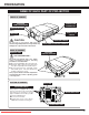
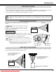
PREPARATION NAME OF EACH PART OF PROJECTOR FRONT OF CABINET INFRARED REMOTE RECEIVER POWER CORD CONNECTOR PROJECTION LENS (Option) MAIN ON / OFF SWITCH LENS CAP (Option) CAUTION Do not turn on a projector with lens cap attached. High temperature from light beam may damage lens cap and result in fire hazard. CARRYING HANDLE LEVEL AND TILT ADJUST HANDLE BACK OF CABINET EXHAUST VENT INFRARED REMOTE RECEIVER HOT AIR EXHAUSTED ! Air blown from exhaust vent is hot.
PREPARATION SETTING-UP PROJECTOR CONNECTING AC POWER CORD This projector uses nominal input voltages of 120 V or 200-240 V AC. This projector automatically selects correct input voltage. It is designed to work with singlephase power systems having a grounded neutral conductor. To reduce risk of electrical shock, do not plug into any other type of power system. Consult your authorized dealer or service station if you are not sure of type of power supply being in use.
PREPARATION LENS INSTALLATION Before setting up a projector, install Projection Lens on a Projector. 1. Before installation, check where a projector is used and prepare suitable lens. For specifications of Projection Lens, refer to manual separately attached or contact sales dealer where you purchased a projector. 2. For installation, refer to installation manual supplied to a Projector. When moving or setting up a projector, be sure to replace a Lens Cap to protect a surface.
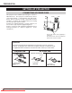
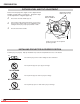
PREPARATION PICTURE LEVEL AND TILT ADJUSTMENT Picture tilt and projection angle can be adjusted with handles on both sides of a projector. Projection angle can be adjusted to 5.7 degrees upper way. 1 Press knob on handle. Handle pop out. 2 Turn handles (right and left) until picture is projected on proper position. Adjust height of rear adjustable feet by rotating them until projector properly stabled on table. 3 Press knob and retract handle. REAR ADJUSTABLE FEET. (Refer to P7).
PREPARATION MOVING PROJECTOR For safety, be sure to hold Carrying Handles on both sides by 2 or more people when moving a projector. Moving it unproperly may result in damage of cabinet or person's injury. Replace lens cap and retract feet to prevent damage to lens and cabinet. 1 Pull up lock buttons on each side of carrying handles and release locks. 2 Pull carrying handles out fully until it's locked (with a click). Move a projector by holding two handles by 2 or more people.
CONNECTING PROJECTOR TERMINALS OF PROJECTOR This projector applies various input/output terminals and 4 terminal slots for expansion to tune to diversity of signals from computers and video equipment. 4-built-in Terminal Slots enable you to arrange desired combinations of input sources just by changing Terminal Boards. For Terminal Boards, contact sales dealer where you purchased a projector.
CONNECTING PROJECTOR INPUT/OUTPUT TERMINALS AND JACKS INPUT 1 INPUT 1, 2, 3, 4 DVI INPUT TERMINAL 5 BNC INPUT JACKS Connect component video output (Cr, Y, Cb or Pr, Y, Pb) from video equipment to R/Pr, G/Y and B/Pb jacks or connect computer output [5 BNC Type (Red, Green, Blue, Horiz. Sync and Vert. Sync.)] from computer to R/Pr, G/Y, B/Pb, H/HV and V jacks. (Refer to P15, 16.) SERIAL PORT IN AUDIO INPUT JACKS Connect computer output (Digital/Analog DVI-I type) to this terminal. (Refer to P15.
CONNECTING PROJECTOR USB PORT (Series B) SERIAL PORT IN TERMINAL This port is used to service this projector. Connect USB port of computer to this port. If you control a projector by computer, you must connect a cable (not provided) from your computer to this terminal. SERIAL PORT OUT TERMINAL SERIAL PORT IN AUDIO L R DVI CONTROL PORT (MONO) AUDIO R/Pr G/Y B/Pb H/HV V R CONTROL PORT INPUT 2 SERIAL PORT OUT INPUT 1 This terminal outputs signal from SERIAL PORT IN.
CONNECTING PROJECTOR CONNECTING TO COMPUTER Cables used for connection (✽ = Cables are not supplied with this projector.) • VGA Cable (HDB 15 pin) • DVI Cable ✽ • BNC Cable (BNC x 5) ✽ • Audio Cables (RCA x 2) ✽ NOTE : When connecting cable, power cords of both a projector and external equipment should be disconnected from AC outlet. Turn a projector and peripheral equipment on before computer is switched on.
CONNECTING PROJECTOR CONNECTING TO VIDEO EQUIPMENT Cables used for connection • Video Cable (BNC x 1, BNC x 2 or BNC x 3) ✽ • HDB 15 pin-Scart 21 pin Cable ✽ • S-VIDEO Cable ✽ (✽ = Cables are not supplied with this projector.) • DVI Cable ✽ • DVI-VGA Adapter ✽ • Audio Cable (RCA x 2) ✽ Component video output equipment. Video Source (example) Video Cassette Recorder Composite Video Output Component Video Output Separate Y/C Video Output Y (such as DVD player or high-definition TV source.
BEFORE OPERATION SIDE CONTROLS AND INDICATORS REAR INDICATORS SIDE CONTROLS FRONT INDICATORS SIDE CONTROLS ZOOM BUTTONS FOCUS BUTTONS POWER ON–OFF BUTTON Used to adjust zoom. (P24) Used to adjust focus. (P24) Used to turn a projector on or off. (P23) ZOOM FOCUS ON-OFF MENU BUTTON LENS SHIFT BUTTON Used to open or close MENU operation. (P21, 22) Used to select LENS SHIFT function. (P24) SELECT BUTTON LENS SHIFT MENU Used to execute item selected.
BEFORE OPERATION INDICATORS FRONT INDICATORS LAMP READY LAMP REPLACE WARNING TEMP. LAMP REPLACE INDICATOR WARNING TEMP. INDICATOR This LAMP REPLACE indicator lights yellow when any of Projection Lamps is nearing its end, and flashes when any of them becomes out. Check which lamp needs to be replaced on Lamp Status Display. (P42-44, 50) This indicator flashes red when internal projector temperature is too high.
BEFORE OPERATION OPERATION OF REMOTE CONTROL AUTO PC ADJ. BUTTON LIGHT BUTTON Lights the buttons on the remote control for about 10 seconds. Used to operate AUTO PC Adjustment function. (P28) POWER ON-OFF BUTTON Used to turn projector on or off. (P23) NO SHOW BUTTON Used to turn picture into black image. (P25) MENU BUTTON Used to select MENU operation. (P21, 22) POINT (UP / DOWN / LEFT / RIGHT) BUTTONS Used to select an item or adjust value in ON-SCREEN MENU.
BEFORE OPERATION REMOTE CONTROL BATTERIES INSTALLATION 1 Remove battery compartment lid. 2 Slide batteries into compartment. 3 Replace compartment lid. Two AA size batteries For correct polarity (+ and –), be sure battery terminals are in contact with pins in compartment. Pull up lid and remove it. To insure safe operation, please observe following precautions : ● Use (2) AA or R06 type alkaline batteries. ● Replace two batteries at same time. ● Do not use a new battery with an used battery.
BEFORE OPERATION OPERATING ON-SCREEN MENU HOW TO OPERATE ON-SCREEN MENU You can control and adjust this projector through ON-SCREEN MENU. Refer to following pages to operate each adjustment on ON-SCREEN MENU. REMOTE CONTROL UNIT 1 DISPLAY MENU Press MENU button to display ON-SCREEN MENU. POINT BUTTONS Used to move a Pointer UP/ DOWN/ RIGHT/ LEFT. 2 MOVING POINTER Move pointer (✽ see below) or adjust value of item by pressing POINT button(s) on Side Control or on Remote Control Unit.
BEFORE OPERATION MENU BAR FOR PC SOURCE Press MENU BUTTON while connecting to PC input source. IMAGE SELECT MENU SCREEN MENU Used to adjust size of image. [Normal / True / Wide / Digital zoom +/–] (Refer to P33) GUIDE WINDOW PC SYSTEM MENU Shows selected item of ONSCREEN MENU. Used to select computer system. (Refer to P27) Used to select image level among Standard, Real and Image 1 ~ 4.
BASIC OPERATION TURNING ON / OFF PROJECTOR TURNING ON PROJECTOR 1 Complete peripheral connections (with Computer, VCR, etc.) before turning on projector. (Refer to "CONNECTING TO PROJECTOR" on Pages 13~16 for connecting that equipment.) LAMP STATUS INPUT 1 2 Connect a projector's AC Power Cord into a wall outlet and turn MAIN ON/OFF SWITCH to ON. LAMP indicator lights RED, and READY indicator lights GREEN. 3 Press POWER ON-OFF button on Side Control or on Remote Control Unit to ON.
BASIC OPERATION ADJUSTING SCREEN ZOOM ADJUSTMENT 1 Press ZOOM ▲/▼ button on Side Control or on Remote Control Unit. Message “Zoom” is displayed. 2 Press ZOOM ▲ button to make image larger, and press ZOOM ▼ button to make image smaller. Zoom Message disappears after 4 seconds. FOCUS ADJUSTMENT 1 Press FOCUS ▲/▼ button on Side Control or on Remote Control Unit. Message “Focus” is displayed. 2 Adjust focus of image by pressing FOCUS ▲/▼ button(s) . Focus Message disappears after 4 seconds.
BASIC OPERATION PICTURE FREEZE FUNCTION Press FREEZE button on Remote Control Unit to freeze picture on-screen. To cancel FREEZE function, press FREEZE button again or press any other button except POINT UP/DOWN/LEFT/RIGHT and SELECT button. NO SHOW FUNCTION Press NO SHOW button on Remote Control Unit to black out a image. To restore to normal, press NO SHOW button again or press any other button except POINT UP/DOWN/LEFT/RIGHT and SELECT button. No show Message disappears after 4 seconds.
COMPUTER INPUT SELECTING INPUT SOURCE DIRECT OPERATION Select INPUT source by pressing INPUT 1/2, INPUT 3/4 or INPUT 1 - INPUT 4 buttons on Side Control or on Remote Control Unit. INPUT 1/2 button INPUT 3/4 button INPUT 1 INPUT 3 INPUT 2 INPUT 4 MENU OPERATION 1 2 Press MENU button and ON-SCREEN MENU will appear. Press POINT LEFT/RIGHT buttons to select Input and press SELECT button. Another dialog box INPUT SELECT Menu will appear.
COMPUTER INPUT WHEN SELECT INPUT 2 (5 BNC INPUT JACKS ) When connect a computer output [5 BNC Type (Red, Green, Blue, Horiz. Sync and Vert. Sync.)] from a computer to R/Pr, G/Y, B/Pb, H/HV and V jacks. INPUT MENU INPUT Menu icon 1 Press MENU button and ON-SCREEN MENU will appear. Press POINT LEFT/RIGHT button to move a red frame pointer to INPUT Menu icon. 2 Press POINT DOWN button to move a red arrow pointer to Input 2 and then press SELECT button. Source Select Menu will appear.
COMPUTER INPUT PC ADJUSTMENT AUTO PC ADJUSTMENT Auto PC Adjustment function is provided to automatically adjust Fine sync, Total dots and Picture Position to conform to your computer. Auto PC Adjustment function can be operated as follows. Auto PC Adj. 1 Press MENU button and ON-SCREEN MENU will appear. Press POINT LEFT/RIGHT button to move a red frame pointer to PC ADJUST Menu icon. 2 Press POINT DOWN button to move a red frame pointer to AUTO PC Adj. icon and then press SELECT button twice.
COMPUTER INPUT MANUAL PC ADJUSTMENT This projector can automatically tune to display signals from most personal computers currently distributed. However, some computers employ special signal formats which are different from standard ones and may not be tuned by Multi-Scan system of this projector. If this happens, projector cannot reproduce a proper image and image may be recognized as a flickering picture, a non-synchronized picture, a non-centered picture or a skewed picture.
COMPUTER INPUT Display area Selects area displayed with this projector. Select resolution at Display area dialog box. Press SELECT button at Display area icon and Display area dialog box appears. Display area H Display area Adjustment of horizontal area displayed with this projector. Press POINT LEFT/RIGHT button(s) to decrease/increase value and then press SELECT button. Display area V Adjustment of vertical area displayed with this projector.
COMPUTER INPUT PICTURE IMAGE ADJUSTMENT IMAGE LEVEL SELECT (DIRECT) Select image level among Standard, Real, Image 1, Image 2, Image 3 and Image 4 by pressing IMAGE/IMAGE SEL. button on Side Control or on Remote Control Unit. IMAGE button Standard Real Standard Normal picture level preset on this projector. Image 1 Real Picture level with improved halftone for graphics. Image 2 IMAGE 1~4 User preset picture adjustment in IMAGE ADJUST Menu (P32).
COMPUTER INPUT IMAGE LEVEL ADJUSTMENT 1 Press MENU button and ON-SCREEN MENU will appear. Press POINT LEFT/RIGHT buttons to move a red frame pointer to IMAGE ADJUST Menu icon. 2 Press POINT DOWN button to move a red frame pointer to item that you want to adjust and then press SELECT button. Level of each item is displayed. Adjust each level by pressing POINT LEFT/RIGHT button(s). Contrast Press POINT LEFT button to decrease contrast, and POINT RIGHT button to increase contrast. (From 0 to 63.
COMPUTER INPUT PICTURE SCREEN ADJUSTMENT This projector has a picture screen resize function, which enables you to display desirable image size. 1 Press MENU button and ON-SCREEN MENU will appear. Press POINT LEFT/RIGHT button(s) to move a red frame pointer to SCREEN Menu icon. 2 Press POINT DOWN button and move a red frame pointer to function that you want to select and then press SELECT button. SCREEN MENU SCREEN Menu icon Move a red frame to function and press SELECT button.
VIDEO INPUT SELECTING INPUT SOURCE DIRECT OPERATION Select INPUT source by pressing INPUT 1/2, INPUT 3/4 or INPUT 1 - INPUT 4 buttons on Side Control or on Remote Control Unit. INPUT 1/2 button INPUT 3/4 button INPUT 1 INPUT 3 INPUT 2 INPUT 4 MENU OPERATION Press MENU button and ON-SCREEN MENU will appear. Press POINT LEFT/RIGHT buttons to select Input and press SELECT button. Another dialog box INPUT SELECT Menu will appear.
VIDEO INPUT SELECTING VIDEO SYSTEM 1 Press MENU button and ON-SCREEN MENU will appear. Press POINT LEFT/RIGHT buttons to move a red frame pointer to AV SYSTEM Menu icon. 2 Press POINT DOWN button to move a red arrow pointer to system that you want to select and then press SELECT button. VIDEO JACK OR S-VIDEO JACK Auto Projector automatically detects incoming Video system, and adjusts itself to optimize its performance. When Video System is PAL-M or PAL-N, select system manually first.
VIDEO INPUT PICTURE IMAGE ADJUSTMENT IMAGE LEVEL SELECT (DIRECT) Select image level among Standard, Cinema, Image 1, Image 2, Image 3 and Image 4 by pressing IMAGE/IMAGE SEL. button on Side Control or on Remote Control Unit. IMAGE button Standard Cinema Standard Normal picture level preset on this projector. Image 1 Cinema Picture level adjusted for picture with fine tone. Image 2 IMAGE 1~4 User preset picture adjustment in IMAGE ADJUST Menu (P38).
VIDEO INPUT IMAGE LEVEL ADJUSTMENT 1 Press MENU button and ON-SCREEN MENU will appear. Press POINT LEFT/RIGHT button(s) to move a red frame pointer to IMAGE ADJUST Menu icon. 2 Press POINT DOWN button to move a red frame pointer to item that you want to adjust and then press SELECT button. Level of each item is displayed. Adjust each level by pressing POINT LEFT/RIGHT button(s). IMAGE ADJUST MENU IMAGE ADJUST Move a red frame pointer to Menu icon item to be selected and then press SELECT button.
VIDEO INPUT 3 Store To store adjustment data, move a red frame pointer to Store icon and press SELECT button. Image Level Menu will appear. Move a red frame pointer to Image Level 1 to 4 and then press SELECT button. Image Level Menu Move a red frame pointer to image icon to be set and then press SELECT button. Other icons operates as follows. Reset Reset all adjustment to previous figure. Quit Store icon Closes IMAGE ADJUST MENU.
SETTING SETTING MENU 1 Press MENU button and ON-SCREEN MENU will appear. Press POINT LEFT/RIGHT button(s) to move a red-frame pointer to SETTING icon. 2 Press POINT DOWN button to move a red-frame pointer to item that you want to set and then press SELECT button. Setting dialog box appears. SETTING MENU Set a red frame pointer to item and press SELECT button.
SETTING Power management This function turns Projection Lamp off when this projector detects signal interruption and is not used for a certain period in order to reduce power consumption and maintain Lamp-life. (This projector is shipped with this function ON.) Power Management function operates to turn Projection Lamp off when input signal is interrupted and any button is not pressed over 5 minutes. This function operates as follows; 1.
SETTING Remote control This projector provides eight different remote control codes (Code 1-Code 8); the factory-set, initial code (Code 1) and the other seven codes (Code 2 to Code 8). This switching function prevents remote control interference when operating several projectors or video equipment at the same time. For example operating the projector in “Code 7”, both the projector and the remote control must be switched to “Code 7”.
APPENDIX MAINTENANCE WARNING TEMP. INDICATOR The Warning Temp. Indicator flashes red to let you know the internal temperature of the projector exceeds the normal level. If the temperature goes up further, the projector will be turned off automatically and the Ready indicator will go out. (The Warning Temp. Indicator continues flashing.
APPENDIX LAMP MANAGEMENT This Projector is equipped with 4 Projection Lamps to ensure brighter image and those lamps are controlled by Lamp Management Function. Lamp Management Function detects status of all lamps and shows status on screen or on LAMP REPLACE indicator. This function also automatically controls Lamp Mode when any of lamps is out for end of life or malfunctions.
APPENDIX LAMP REPLACEMENT When the life of the Projection Lamp of this projector draws to an end, the LAMP REPLACE indicator lights yellow. If this indicator lights yellow, replace the projection lamp with a new one promptly. FRONT INDICATORS REAR INDICATORS LAMP READY WARNING: TURN OFF THE UV LAMP BEFORE OPENING THE LAMP COVER. LAMP REPLACE LAMP READY WARNI TEMP.NG LA P REPLM ACE WARNING TEMP.
APPENDIX ORDER REPLACEMENT LAMP Replacement Lamp can be ordered through your dealer. When ordering a Projection Lamp, give the following information to the dealer. ● Model No. of your projector ● Replacement Lamp Type No. : : LC-XT4U/E POA-LMP100 (Service Parts No. 610 327 4928) LAMP REPLACE COUNTER Be sure to reset Lamp Counter when Lamp Assembly is replaced. When Lamp Replace Counter is reset, LAMP REPLACE indicator stops lighting.
APPENDIX LAMP HANDLING PRECAUTIONS This projector uses a high-pressure lamp which must be handled carefully and properly. Improper handling may result in accidents, injury, or create a fire hazard. ● Lamp lifetime may differ from lamp to lamp and according to the environment of use. There is no guarantee of the same lifetime for each lamp. Some lamps may fail or terminate their lifetime in a shorter period of time than other similar lamps. ● If the projector indicates that the lamp should be replaced, i.
APPENDIX TROUBLESHOOTING Before calling your dealer or service center for assistance, check matters below once again. 1. Make sure you have connected a projector to your computer or video equipment as described in section "CONNECTING PROJECTOR" on pages 13 ~ 16. 2. Check cable connection. Verify that all computer, video and power cord are properly connected. 3. Verify that all power is switched on. 4. If a projector still does not produce an image, re-start your computer. 5.
APPENDIX MENU TREE Computer Input/Video Input Input Input 1 Go to System (1) RGB (Analog) RGB (Scart) RGB (PC Digital) RGB (AV HDCP) Input 2 Input 3 RGB Go to System (1) Y, Pb/Cb, Pr/Cr Go to System (3) Video Go to System (2) S-Video Go to System (2) Y/C Go to System (2) Go to System (1) Input 4 Computer Input System (1) PC Adjust SVGA 1 SVGA 2 SVGA 3 MODE 1 MODE 2 Auto PC Adj. Fine sync.
APPENDIX Computer Input/Video Input Video Input Setting System (2) Auto PAL SECAM NTSC NTSC 4.
APPENDIX INDICATORS AND PROJECTOR CONDITION Check the Indicators for projector condition. Indicators LAMP REPLACE yellow WARNING TEMP. red READY LAMP green red Projector Condition The projector is OFF. (The MAIN switch OFF position or the AC Power Cord is unplugged.) ※ The projector is READY to be turned on with the POWER ONOFF button. ※ The projector is operating normally. ※ The temperature inside the projector is abnormally high. The projector cannot be turned on.
APPENDIX COMPATIBLE COMPUTER SPECIFICATIONS Basically this projector can accept a signal from all computers with V, H-Frequency mentioned below and less than 230 MHz of Dot Clock.
APPENDIX When a input signal is digital from DVI terminal, refer to chart below. ON-SCREEN DISPLAY RESOLUTION D-VGA D-480p D-575p D-SVGA D-XGA D-WXGA 1 D-WXGA 2 D-WXGA 3 D-WXGA 4 D-WXGA 5 640 x 480 720 x 480 (Progressive) 768 x 575 (Progressive) 800 x 600 1024 x 768 1366 x 768 1360 x 768 1376 x 768 1360 x 768 1368 x 768 H-Freq. (kHz) V-Freq. (Hz) ON-SCREEN DISPLAY 31.47 31.47 31.25 37.879 43.363 48.36 47.70 48.36 56.16 46.50 59.94 59.88 50.00 60.32 60.00 60.00 60.00 60.00 72.00 50.
APPENDIX TECHNICAL SPECIFICATIONS Projector Type Dimensions (W x H x D) Net Weight LCD Panel System Panel Resolution Number of Pixels Color System High Definition TV Signal Motorized Lens Shift Scanning Frequency Horizontal Resolution Projection Lamp Input 1 Jacks Multi-media Projector 22.9" x 10" x 30.9" (581 mm x 252 mm x 783 mm) 80.3 lbs (36.5 kg) 1.8" TFT Active Matrix type, 3 panels 1024 x 768 dots 2,359,296 (1024 x 768 x 3 panels) PAL, SECAM, NTSC, NTSC4.
APPENDIX CONFIGURATIONS OF TERMINALS DVI-I TERMINAL (DIGITAL/ANALOG) This terminal accepts only Digital (TMDS) or Analog (RGB) output signal. Connect display output terminal of computer to this terminal with DVI cable (not supplied). Pin Configuration C1 C2 1 2 3 4 5 6 7 8 9 10 11 12 13 14 15 16 17 18 19 20 21 22 23 24 C3 C4 C5 C1 C2 C3 C4 C5 Analog Red Input Analog Green Input Analog Blue Input Analog Horiz. sync Analog Ground (R/G/B) 1 2 3 4 5 6 7 8 T.M.D.S. Data2– T.M.D.S. Data2+ T.M.D.S.
APPENDIX DIMENSIONS Unit : inch (mm) 22.87 (581.0) 10.15 (258.0) 9.90 (251.5) 5.18 (131.5) 17.56 (446.0) 17.56 (446.0) 7.01 (178.0) 7.01 (178.0) 9.90 (251.5) 22.87 (581.0) 5.7° 2.36 (60.0) 4.23 (107.5) 14.74 (374.5) 9.72 (247.0) 22.93 (582.5) 30.83 (783.0) 10.61 (269.5) 3.26 (82.8) 6.81 (173.0) 1.38 (35.0) 1.57 (40.0) 8.27 (210.0) 8.27 (210.0) Screw Holes for Ceiling Mount Screws: 9-M8 Depth: 0.315 (8.0) 8.62 (219.0) Downloaded From projector-manual.com EIKI Manuals 9.25 (235.
A-key to better communications U.S.A. Canada EIKI International, Inc. 30251 Esperanza Rancho Santa Margarita CA 92688-2132 U.S.A. Tel : 800-242-3454 (949)-457-0200 Fax : 800-457-3454 (949)-457-7878 E-Mail : usa@eiki.com EIKI CANADA - Eiki International, Inc. P.O. Box 156, 310 First St. - Unit 2, Midland, ON, L4R 4K8, Canada Tel : 800-563-3454 (705)-527-4084 Fax : 800-567-4069 (705)-527-4087 E-Mail : canada@eiki.