MULTIMEDIA PROJECTOR MODEL LC-XGC500 LC-XGC500L ✽ ✽ Projection lens is optional.
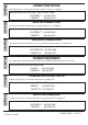
English CORRECTION NOTICE The following is a correction to the owner's manual on page 61. Replacement Filter Cartridge Service Parts Code: INCORRECT 610 342 5764 CORRECT 610 342 9571 Français AVIS DE CORRECTION Voici une correction apportée au mode d'emploi à la page 61.
Features and Design ◆ Functionally Rich ◆ This projector has many useful functions such as lens shifting, ceiling and rear projection, perpendicular omnidirectional projection, variety of lens options, etc. ◆ Auto Lamp Selection System Operation menu is available in 12 languages; English, German, French, Italian, Spanish, Portuguese, Dutch, Swedish, Russian, Chinese, Korean, and Japanese (p.49).
Table of Contents Features and Design . . . . . . . . . . . . . . . . Table of Contents . . . . . . . . . . . . . . . . . . . To the Owner . . . . . . . . . . . . . . . . . . . . . . Safety Instructions . . . . . . . . . . . . . . . . . 2 3 4 5 Air Circulation 6 Installing the Projector in Proper Directions 7 Positioning Precautions 7 Moving the Projector 8 Cautions in Handling the Projector 8 Compliance . . . . . . .
To the Owner Before installing and operating the projector, read this manual thoroughly. The projector provides many convenient features and functions. Operating the projector properly enables you to manage those features and maintains it in good condition for many years to come. Improper operation may result in not only shortening the product life, but also malfunctions, fire hazard, or other accidents.
Safety Instructions All the safety and operating instructions should be read before the product is operated. Do not install the projector near the ventilation duct of airconditioning equipment. Read all of the instructions given here and retain them for later use. Unplug this projector from AC power supply before cleaning. Do not use liquid or aerosol cleaners. Use a damp cloth for cleaning. This projector should be operated only from the type of power source indicated on the marking label.
Safety Instructions Air Circulation IMPORTANT! Openings in the cabinet are provided for ventilation. To ensure reliable operation of the product and to protect it from overheating, these openings must not be blocked or covered. CAUTION Hot air is exhausted from the exhaust vent. When using or installing the projector, the following precautions should be taken. – Do not put any flammable object or spray can near the projector, hot air is exhausted from the air vents.
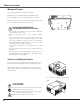
Safety Instructions Installing the Projector in Proper Directions Use the projector properly in specified positions. Improper positioning may reduce the lamp life and result in severe accident or fire hazard. This projector can project the picture in upward, downward, or inclined position in perpendicular direction to the horizontal plane. ✔Note: • To inverse or reverse the image, set the ceiling function to “On.” (p.
Safety Instructions Moving the Projector Use the hand grip when moving the projector. Replace the lens cap and retract the adjustable feet to prevent damage to the lens and cabinet when carrying. When the projector is not in use for an extended period, put it into a suitable case to protect the projector. CAUTION IN CARRYING OR TRANSPORTING THE PROJECTOR – Do not drop or bump the projector, otherwise damages or malfunctions may result. – When carrying the projector, use a suitable carrying case.
Compliance Federal Communications Commission Notice This equipment has been tested and found to comply with the limits for a Class B digital device, pursuant to Part 15 of the FCC Rules. These limits are designed to provide reasonable protection against harmful interference in a residential installation. This equipment generates, uses, and can radiate radio frequency energy and, if not installed and used in accordance with the instructions, may cause harmful interference to radio communications.
Part Names and Functions q w e r t y u i o !0 Front q w r e Lens Release Button Infrared Remote Receiver (Top&Front) Terminals and Connectors Top Controls and Indicators Lens Cap (for LC-XGC500) Speaker Projection Lens (for LC-XGC500) Adjustable Feet Power Cord Connector Optional Parts Attachment CAUTION ✽ o t y Back y u !0 i !2 !3 !1 Do not turn on the projector with the lens cap attached. High temperature from light beam may damage the lens cap and result in fire hazard.
Part Names and Functions Side Terminal q w e r t y i u o q COMPUTER INPUT TERMINAL (DIGITAL) Connect the computer output signal (Digital DVI-D type) to this terminal. The HDTV (HDCP compatible) signal can also be connected (p.20). w COMPUTER INPUT TERMINAL (ANALOG) Connect the computer (or RGB scart) output signal to this terminal (p.20). e AUDIO MONITOR OUTPUT JACK (VARIABLE) This jack outputs the audio signal from computer or video equipment to external audio equipment (p.22).
Part Names and Functions Side Terminal !0 !1 !2 !3 !0 USB CONNECTOR (Series B) Use this connector when controlling a computer with the remote control of the projector. Connect the USB terminal of your computer to this connector with the supplied USB cable (p.20). !1 R/C JACK When using the wired remote control, connect the wired remote control to this jack with a remote control cable. !2 VIDEO INPUT JACK Connect the composite video output signal from video equipment to this jack (p.21).
Part Names and Functions Top Control q o w !0 e !1 r t !2 y !3 u i q WARNING TEMP. indicator – Lights red light when the projector detects an abnormal condition or the filter cartridge is not installed. – Blinks red when the internal temperature of the projector exceeds the operating range (pp.66, 75). w LAMP 1 REPLACE indicator urn yellow when the life of the projection lamp1 draws T to an end. (pp.63-64, 74) e SHUTTER indicator Light blue when the shutter is closed. (pp.
Part Names and Functions Remote Control r e w q t y !2 u !1 i o !0 q STAND-BY button Turn the projector off (p.25). w Wired Remote jack Connect the remote control cable to this jack when using as a wired remote control. o Point ed 7 8 ( VOLUME + / – ) buttons – Select an item or adjust the value in the OnScreen Menu (p.26). – Pan the image in Digital zoom + mode (p.47). – Adjust the volume level (with Point 7 8 buttons) (p.29).
Part Names and Functions Remote Control @6 !3 @5 !4 @4 !5 @3 @7 !6 For PIN code and remote control code. @2 !7 @1 !8 @0 !9 !3 MENU button Open or close the On-Screen Menu (p.26). @0 FOCUS button Adjust the focus (pp.28,30). !4 P-TIMER button Operate the P-timer function (p.31). @1 SHUTTER button Close the built-in shutter for light blocking.(pp.28,56) !5 D.ZOOM button Select the Digital zoom +/- mode and resize the image (pp.30,47). @2 KEYSTONE button Correct keystone distortion (p.31).
Part Names and Functions Remote Control Battery Installation 1 Open the battery compartment lid. 2 Install new batteries into the compartment. Press the lid downward and slide it. 3 Replace the compartment lid. Two AAA size batteries For correct polarity (+ and –), be sure battery terminals are in contact with pins in the compartment. To ensure safe operation, please observe the following precautions : ● Use two (2) AAA or LR03 type alkaline batteries. ● Always replace batteries in sets.
Part Names and Functions Remote Control Code The eight different remote control codes (Code 1–Code 8) are assigned to this projector. Switching the remote control codes prevents interference from other remote controls when several projectors or video equipment next to each other are operated at the same time. Change the remote control code for the projector first before changing that for the remote control. See “Remote control” in the Setting Menu on page 53.
Installation Positioning the Projector (for LC-XGC500) For projector positioning, see the figures below. The projector should be set perpendicularly to the plane of the screen. ✔Notes: • The brightness in the room has a great influence on picture quality. It is recommended to limit ambient lighting in order to obtain the best image. • All measurements are approximate and may vary from the actual sizes. (Inch Diagonal) 32.8' (10.0m) 22.0' (6.7m) 300” Max. Zoom 230” Min. Zoom 16.4' (5.0m) 10.8' (3.
Installation Lens Installation When replacing the lens or using an optional lens, install the lens by following the instructions below. Ask the sales dealer for detailed information of the optional lens specifications. Lens Release button Removing the lens 1 Shift the lens to the center position by using the Lens shift function (see page 28). 2 Turn off the projector and unplug the AC power cord.
Installation Connecting to a Computer (Digital and Analog RGB) Cables used for connection )( =Cables are not supplied with this projector.
Installation Connecting to Video Equipment (Video, S-video, Component and RGB Scart) Cables used for connection • Video Cable (RCA x 1) • VGA-Scart Cable • S-VIDEO Cable • BNC Cable • DVI-Digital Cable (Cables are not supplied with the projector.
Installation Connecting for Audio Signal Cables used for connection • Audio Cable (Mini Plug [stereo] x 2) • Audio Cable (RCA x 2) (Cables are not supplied with the projector.) MONITOR OUT and AUDIO OUT Specifications Selected Input Input 1 Input 2 Input 3 Network MONITOR OUT Terminal Input 1(D-Sub) Input 2(5-BNC) Input 1 or Input 2* Input 1 or Input 2* AUDIO OUT Terminal Input 1 Input 2 Input 3 NIL * Between Input1 and Input2, the last selected Input is output to MONITOR OUT terminal.
Installation Connecting the AC Power Cord This projector uses nominal input voltages of 100–120 V or 200–240 V AC and it automatically selects the correct input voltage. It is designed to work with single-phase power systems having a grounded neutral conductor. To reduce the risk of electrical shock, do not plug into any other type of power system. If you are not sure of the type of power being supplied, consult your authorized dealer or service station.
Basic Operation Turning On the Projector 1 Complete peripheral connections (with a computer, VCR, etc.) before turning on the projector. 2 Connect the projector’s AC power cord into an AC outlet. The POWER indicator lights red. 3 Press the ON/STAND-BY button on the top control or the ON button on the remote control. The POWER indicator turns green and the cooling fans start to operate. The preparation display appears on the screen and the count down starts.
Basic Operation Turning Off the Projector 1 Press the ON/STAND-BY button on the top control or the STAND-BY button on the remote control, and “Power off?” appears on the screen. 2 Press the ON/STAND-BY button or the STAND-BY button on the remote control again to turn off the projector. The POWER indicator starts to blink red. After the projector is turned off, the cooling fans operates for 90 seconds. During the POWER indicator is blinking, you cannot turn on the projector.
Basic Operation How to Operate the On-Screen Menu The projector can be adjusted or set via the On-Screen Menu. For each adjustment and setting procedure, refer to the respective sections in this manual. Top Control MENU button 1 Press the MENU button on the top control or the remote control to display the On-Screen Menu. POINT buttons 2 Use the Point 7 8 buttons to select a Menu icon. Use the Point ed buttons to select an item in the selected menu.
Basic Operation Menu Bar For detailed functions of each menu, see “Menu Tree” on pages 71-72. *The menu bar displays changes depending on the input signals. Guide Window System [PC Adjust] Image Adjust Setting Menu Show the selected Menu of the OnScreen Menu. Select a computer or video system mode (pp.36, 37). Adjust parameters to match with an input signal format (pp.38–40) Set the projector’s operating configurations (pp.49–59).
Basic Operation Operating with Projector Control Lens Operation Top Control The following lens operation can be made with the Lens button on the top control. Press the Lens button to enter each lens operation mode. The selected adjustment display appears on the screen. Zoom ➜ Focus ➜ Lens Shift ➜ SHUTTER button LENS button MENU button POINT buttons ••••• Zoom Adjustment Display “Zoom” on the screen. Use the Point ed buttons to zoom in and out the image.
Basic Operation Sound Adjustment Direct Operation Top Control VOLUME +/– buttons Volume Press the VOLUME+/– buttons on the top control or on the remote control to adjust the volume. The volume dialog box appears on the screen for a few seconds. Mute Press the MUTE button on the remote control to temporarily turn off the sound. To turn the sound back on, press the MUTE button again or press the VOLUME +/– buttons. The Mute function is also effective for the AUDIO OUT jack.
Basic Operation Operating with Remote Control Using the remote control for some frequently used operations is advisable. Just pressing one of the buttons enables you to make the desired operation quickly without calling up the On-Screen Menu. FREEZE button Press the FREEZE button on the remote control to freeze the picture on the screen. To cancel the Freeze function, press the FREEZE button again or press any other button.
Basic Operation SHUTTER button Remote Control See pages 28 and 56 for details. P-TIMER button KEYSTONE button SHUTTER button ✔Note: • See the previous page for the description of other buttons. P-TIMER button Press the P-TIMER button on the remote control. The P-Timer display “00:00” appears on the screen and the countdown starts (00:00–59:59). To stop the countdown, press the P-TIMER button. To cancel the P-Timer function, press the P-TIMER button again.
Basic Operation Laser Pointer Function This remote control emits a laser beam from the laser light window. Press the LASER button to activate the laser pointer. The signal emission indicator lights red and the red laser beam is emitted. If the LASER button is pressed for more than one minute or if it is released, the laser light goes off. The laser emitted is a Class II laser. Do not look into the laser light window or point the laser beam at yourself or other people.
Basic Operation Wireless Mouse Operation The remote control can be used as a wireless mouse for your computer. 1 2 Before operating the wireless mouse, connect your computer and the projector with the supplied USB cable (p. 20). When the Pointer function is used, the wireless mouse is not available. When a USB cable is connected to the computer and the projector, turn on the projector first, then the computer. If you turn on the computer first, the wireless mouse function may not operate properly.
Input Selection Input Remote Control Remote Control button operation INPUT 1 button Input 1 INPUT buttons RGB (PC analog) RGB (Scart) Remote Control Operation Press the INPUT 1, INPUT 2, or INPUT 3 buttons on the remote control. The input source appears on the screen as you press each button. Select the connected input source.
Input Selection Input Source Selection Menu Operation 1 Press the MENU button to display the On-Screen Menu. Use the Point 7 8 buttons to move the red frame pointer to the Input Menu icon. 2 Use the Point ed buttons to move the red arrow pointer to the desired input and then press the SELECT button. The signal format menu appears. 3 Use the Point ed buttons to select the desired signal format and then press the SELECT button.
Input Selection Video System Selection 1 Press the MENU button to display the On-Screen Menu. Use the Point 7 8 buttons to move the red frame pointer to the AV System Menu icon. 2 Use the Point ed buttons to move the red arrow pointer to the desired system and then press the SELECT button. Video or S-video Auto The projector automatically detects an incoming video system, and adjusts itself to optimize its performance. When Video System is PAL-M or PAL-N, select the system manually.
Computer Adjustment Computer System Selection This projector automatically tunes to various types of computers based on VGA, SVGA, XGA, SXGA, WXGA, UXGA or WUXGA with its Multi-scan system and Auto PC Adjustment. If a computer is selected as a signal source, this projector automatically detects the signal format and tunes to project a proper image without any additional settings. (Signal formats provided in this projector are shown on pages 76–77.
Computer Adjustment Auto PC Adjustment Auto PC Adjustment function is provided to automatically adjust Fine sync, Total dots, Horizontal and Vertical positions to conform to your computer. Direct Operation Remote Control The Auto PC adjustment function can be operated directly by pressing the AUTO PC button on the remote control. AUTO PC button Menu Operation Auto PC Adj. 1 Press the MENU button to display the On-Screen Menu.
Computer Adjustment Manual PC Adjustment Some computers employ special signal formats which may not be tuned by Multi-scan system of this projector. Manual PC Adjustment enables you to precisely adjust several parameters to match those signal formats. The projector has 10 independent memory areas to store those parameters manually adjusted. It allows you to recall the setting for a specific computer. 1 Press the MENU button to display the On-Screen Menu.
Computer Adjustment Display area H Use the Point 7 8 buttons to adjust the horizontal area displayed by this projector. Display area V Use the Point 7 8 buttons to adjust the vertical area displayed by this projector. Reset Move the red frame pointer to the desired item and press the SELECT button. To reset the adjusted data, select Reset and press the SELECT button. A confirmation box appears and then select [Yes]. All adjustments will return to their previous figures.
Image Level Selection Image Level Selection 1 Press the MENU button to display the On-Screen Menu. Use the Point 7 8 buttons to move the red frame pointer to the Image Menu icon. 2 Use the Point ed buttons to move the red frame pointer to the desired image level and then press the SELECT button. Dynamic For viewing pictures in a bright room. Image Menu Image Menu icon Move the red frame pointer to the desired image level and press the SELECT button.
Image Adjustment Image Adjustment 1 Press the MENU button to display the On-Screen Menu. Use the Point 7 8 buttons to move the red frame pointer to the Image Adjust Menu icon. 2 Use the Point ed buttons to move the red frame pointer to the desired item and then press the SELECT button to display the adjustment dialog box. Use the Point 7 8 buttons to adjust the setting value. Contrast Press the Point 7 button to decrease the contrast; press the Point 8 button to increase the contrast (from 0 to 63).
Image Adjustment Sharpness Press the Point 7 button to decrease the sharpness of the image; press the Point 8 button to increase the sharpness of the image (from 0 to 15). Gamma Use the Point 7 8 buttons to adjust the gamma value to obtain a better balance of contrast (from 0 to 15). Noise reduction Noise interference on the screen can be reduced. Select one of the following options to get smoother images. Off ��������� Disabled.
Image Adjustment Reset To reset the adjusted data, select Reset and press the SELECT button. A confirmation box appears and then select [Yes]. All adjustments will return to their previous figures. Store To store the adjusted data, select Store and press the SELECT button. Use the Point ed buttons to select one from Image 1 to 4 and press the SELECT button. A confirmation box appears and then select [Yes]. Stored data can be called up by selecting an “Image (1–4)” in the Image Level Selection on page 41.
Screen Adjustment Screen Adjustment 1 Press the MENU button to display the On-Screen Menu. Use the Point 7 8 buttons to move the red frame pointer to the Screen Menu icon. 2 Use the Point ed buttons to move the red frame pointer to the desired function and then press the SELECT button. Keystone Screen Menu Screen Menu icon Move the red frame pointer to the desired function and press the SELECT button.
Screen Adjustment Screen Size Adjustment (Computer Signals) Select the desired screen size that conforms to the input signal source. Normal Screen Menu Provide the image to fit the screen size. Screen Menu icon True Move the red frame pointer to the desired function and press the SELECT button. Provide the image in its original size. When the original image size is larger than the screen size (1024 x 768), the projector enters to the panning mode automatically.
Screen Adjustment For zooming in and out the images Digital zoom + Select Digital zoom +. The On-Screen Menu disappears and “D. zoom +”appears. Press the SELECT button to expand the image size. Use the Point ed7 8 buttons to pan the image. The Panning function can work only when the image is larger than the screen size. You can also enter the Digital zoom + mode by pressing the D.ZOOM button on the remote control. Digital zoom – Select Digital zoom –. The On-Screen Menu disappears and “D. zoom –” appears.
Screen Adjustment Screen Size Adjustment (Video, Component Signals) 1 Press the MENU button to display the On-Screen Menu. Use the Point 7 8 buttons to move the red frame pointer to the Screen Menu icon. 2 Use the Point ed buttons to move the red frame pointer to the desired function and then press the SELECT button. Screen Menu Screen Menu icon Move the red frame pointer to the desired function and press the SELECT button. Normal Provide the image at the 4:3 normal video aspect ratio.
Setting Setting This projector has a Setting menu that allows you to set up the other various functions described below. 1 Press the MENU button to display the On-Screen Menu. Use the Point 7 8 buttons to move the red frame pointer to the Setting Menu icon. 2 Use the Point ed buttons to move the red frame pointer to the desired item and then press the SELECT button. The Setting dialog box appears.
Setting Capture Capture This function enables you to capture an image being projected to use it for a starting-up display or interval of presentations. Select Capture and press the SELECT button. A confirmation box appears and select [Yes] to capture the projected image. After capturing the projected image, go to the Logo select function and set it to “User”. Then the captured image will be displayed the next time you turn on the projector. Select [Yes] to capture the projected image.
Setting Enter a Logo PIN code Use the Point ed buttons on the top control or Number buttons on the remote control to enter a number. When using top control Use the Point ed buttons on the top control to select a number. Press the Point 8 button to fix the number and move the red frame pointer to the next box. The number changes to “✳.” Repeat this step to complete entering a four-digit number. After entering the four-digit number, move the pointer to “Set.
Setting Lamp mode This Projector is equipped with 2 Projection Lamps. This function allows you to choose how to use the lamp as follows. Lamp1............ Always use Lamp 1. Lamp2 ........... Always use Lamp 2. Lamp1/2......... Automatically switch the active lamp from one lamp to the other when the projector is turned Off and On each time the lighting time of a lamp exceeds 10 hours. Set the red frame pointer to the item and press the SELECT button. ✔Note: Use the Point ed buttons to set the Lamp mode.
Setting Filter control You can replace the filter with this function. Press the SELECT button at Filter control to display a confirmation box. To replace, press the SELECT button at “YES” and the electrically operated filter starts to scroll. Pointer ✔Note: • Filter replacement icon and “Please wait...” message appear on the screen when the filter is being scrolled. • The filter cannot be rewound. • When the filter is replaced, the total accumulated time of the filter use is automatically set to 0.
Setting Display This function decides whether to display On-Screen Displays. On ���������������������������� Show all the On-Screen displays. Use this function when you want to project images after the lamp becomes bright enough. The factory default setting is in this option. Countdown Off �������� Show the input image instead of the countdown when turning on the projector. Use this function when you want to project the image as early as possible even when the lamp is not bright enough.
Setting Power management Select one of the following options: Ready ����������������� When the lamp has been fully cooled down, the POWER indicator changes to fast blinking. In this condition, the projection lamp can be turned on if the input signal is reconnected or any button on the top control or remote control is pressed. Shut down ��������� When the lamp has been fully cooled down, the power will be turned off. Off ��������������������� Power management function is off.
Setting Shutter Shutter function is available to block out light to the screen, so that the screen can be used for the other presenters. Protection Prohibits the shutter operation from the remote control and the projector's top control. Remote control ... Selecting "On" prohibits the shutter operation from the remote control. Projector �������� ... Selecting "On" prohibits the shutter operation from the top control.
Setting PIN code lock This function prevents the projector from being operated by unauthorized persons and provides the following setting options for security. Off ����������� Unlocked. On1 ���������� Enter the PIN code every time turning on the projector. On2 ���������� Enter the PIN code to operate the projector once the power cord is disconnected; as long as the AC power cord is connected, the projector can be operated without a PIN code.
Setting Change the PIN code Change the PIN code The PIN code can be changed to your desired four-digit number. Press the Point d buttons to select “PIN code change” and press the SELECT button. The New PIN code input dialog box appears. Set a new PIN code. caution: when you have changed THE PIn code, write down the new pin code in column of the pin code no. memo on page 82, and keep it securely. If you forget your PIN code, the projector can no longer be started.
Setting Filter counter This function is used to set a time for the filter replacement. Use the Point ed buttons to move the red frame pointer to Filter counter and then press the SELECT button. A dialog box appears showing the Used time option and the Scrolls remaining option. Used Time ������������ Show the total accumulated time of the filter use, timer setting option and the Reset options. When the projector reaches a time set in the timer setting, the Filter replacement icon (Fig.
Maintenance and Care Filter Instructions Filter prevents dust from accumulating on the optical elements inside the projector. Should the filter becomes clogged with dust particles, it will reduce cooling fans’ effectiveness and may result in internal heat buildup and adversely affect the life of the projector. This projector has an electrically operated filter which helps you to replace the filter easily.
Maintenance and Care Replacing the Filter Cartridge 1 Turn off the projector, press the Main On/Off Switch to Off and unplug the AC power cord from the AC outlet. 2 First, clean up the dust on the projector and around the air vents. 3 Slide and open the Filter cover. (See the right figure.) 4 Pull out the filter cartridge by holding the finger grip. 5 Put the new one back into the position until it clicks and close the filter cover.
Maintenance and Care Resetting the Filter Counter Filter counter Be sure to reset the Filter counter after replacing the filter cartridge. 1 Press the MENU button to display the On-Screen Menu. Use the Point 7 8 buttons to move the red frame pointer to the Setting Menu icon. 2 Use the Point ed buttons to move the red frame pointer to Filter counter and then press the SELECT button. A dialog box appears showing the Used time option and the Scrolls remaining option.
Maintenance and Care Auto Lamp Selection System This Projector is equipped with 2 Projection Lamps. The Lamp Management Function detects the status of lamps and shows the status on screen or on the LAMP 1/2 REPLACE indicators. This function also automatically controls the Lamp Mode when any of lamps reaches the recommended total hours of use or is out for the end of life or malfunctions.
Maintenance and Care Lamp Replacement Top Control When the total lighting time of a Projection Lamp reaches the recommended total hours of use, the Lamp replacement icon appears on the screen and LAMP 1 / 2 REPLACE indicator lights yellow. Replace the lamp with a new one promptly. The timing when the LAMP 1 / 2 REPLACE indicator should light is depending on the lamp mode.
Maintenance and Care ORDER REPLACEMENT LAMP Replacement lamp can be ordered through your dealer. When ordering, give the following information to the dealer. Model No. of your projector ● Replacement Lamp Type No. ● : LC-XGC500 , LC-XGC500L : POA-LMP125 (Service Parts No. 610 342 2626) LAMP HANDLING PRECAUTIONS This projector uses a high-pressure lamp which must be handled carefully and properly. Improper handling may result in accidents, injury, or create a fire hazard.
Maintenance and Care Warning Indicators The WARNING indicators show the state of the function which protects the projector. Check the state of the WARNING indicators and the POWER indicator to take proper maintenance. The projector is shut down and the WARNING TEMP. indicator is blinking red. When the temperature inside the projector reaches a certain level, the projector will be automatically shut down to protect the inside of the projector.
Maintenance and Care Cleaning the Projection Lens Unplug the AC power cord before cleaning. Gently wipe the projection lens with a cleaning cloth that contains a small amount of non-abrasive camera lens cleaner, or use a lens cleaning paper or commercially available air blower to clean the lens. Avoid using an excessive amount of cleaner. Abrasive cleaners, solvents, or other harsh chemicals might scratch the surface of the lens. When the projector is not in use, replace the lens cap.
Appendix Troubleshooting Before calling your dealer or service center for assistance, check the items below once again. – Make sure you have properly connected the projector to peripheral equipment as described on pages 20–22. – Make sure all equipment is connected to AC outlet and the power is turned on. – When the projector does not project an image from the connected computer, restart the computer.
Appendix – Projecting from the excessive slant angle to the screen may cause keystone distortion and partial imperfect focus. Picture is not bright enough. The color is strange. Image is Left/Right reversed. Image is Top/Bottom reversed. – Check if "Contrast" or "Brightness" are adjusted properly See page 42. – Check if "Image level" is selected properly See page 41. – Check the LAMP 1/2 REPLACE indicators. If it lights, the end of lamp life is approaching.
Appendix Capture function does not work. – Check the connection and the Input signal to see if there is signal. The Remote Control does – not work. – – – – – Check the batteries. Make sure no obstruction is between the projector and remote control. Make sure you are not too far from the projector when using the remote control. Maximum operating range is 16.4’ (5 m). Make sure that the remote control code conforms to the projector’s code. See page 53.
Appendix Menu Tree Input Input 1 RGB (PC analog) Go to System (1) RGB (Scart) RGB (PC digital) RGB (AV HDCP) Quit Input 2 RGB Go to System (1) Video Go to System (3) Component Go to System (2) Quit Input 3 Video Go to System (3) S-video Go to System (3) Quit System (1) System (2) Mode 1 Auto System (3) Auto Mode 2 1080i XGA 1 1035i SECAM ---- 720p NTSC 575p NTSC4.
Appendix PC Adjust Auto PC adj. Fine sync Total dots Horizontal Vertical Current mode Clamp Display area H Display area V Reset Mode free/Store Setting Language 0–31 Logo H-sync freq. V-sync freq.
Appendix Indicators and Projector Condition Check the indicators for the projector condition. The projector is operating normally. Indicators Projector Condition WARNING WARNING SHUTTER LAMP 1/2 POWER REP. FILTER TEMP. blue green / red yellow orange red The projector is off. (The AC power cord is unplugged.) red green green red red green red green ✽ ✽ The projector is in stand-by mode. Press the ON/STANDBY button to turn on the projector. ✽ ✽ The projector is operating normally.
Appendix The projector is detecting abnormal condition. Indicators WARNING WARNING SHUTTER LAMP 1/2 POWER REP. FILTER TEMP. blue green / red yellow orange red ✽ green ✽ ✽ ✽ ✽ The temperature inside the projector is elevated close to the abnormally high level. ✽ The temperature inside the projector is abnormally high. The projector cannot be turned on. When the projector is cooled down enough and the temperature returns to normal, the POWER indicator lights red and the projector can be turned on.
Appendix The projector is detecting abnormal condition. Indicators POWER green / red ✽ WARNING WARNING SHUTTER FILTER TEMP. blue orange red ✽ ✽ ✽ Fig.2 Filter replacement icon Fig.3 red red red red • Fig.2, Fig.3 and Fig.4 icon will not appear when the Display function is set to “Off” (p.54), or during “Freeze” (p.30). The filter cartridge is not installed in the projector. Check the filter compartment to see if the filter cartridge is installed in the projector.
Appendix Compatible Computer Specifications Basically this projector can accept the signal from all computers with the V- and H-Frequency mentioned below and less than 140 MHz of Dot Clock. PC Adjustment is limited when selecting these modes.
Appendix When an input signal is digital from the DVI terminal, refer to the chart below. PC Adjust Menu cannot be selected when Input 1 [RGB (PC digital)] is selected in the Input Menu. ON-SCREEN DISPLAY D-VGA D-480p D-575p D-SVGA D-XGA D-WXGA 1 D-WXGA 2 D-WXGA 3 D-WXGA 4 D-WXGA 5 RESOLUTION 640x480 720x480 768x575 800x600 1024x768 1366x768 1360x768 1376x768 1360x768 1366x768 H-Freq. (kHz) 31.470 31.470 31.250 37.879 43.363 48.360 47.700 48.360 56.160 46.500 V-Freq. (Hz) 59.940 59.880 50.000 60.320 60.
Appendix Technical Specifications Mechanical Information Projector Type Dimensions (W x H x D) Net Weight Feet Adjustment Multi-media Projector 21.66” x 6.89” x. 17.76” (451.0 mm x 175.0 mm x 550.1 mm) 32.4 lbs (14.7 kg) 0˚ to 3.5˚ Panel Resolution LCD Panel System Panel Resolution Number of Pixels 1.
Appendix Accessories Owner’s Manual (CD-ROM) Quick Reference Guide AC Power Cord Remote Control and Batteries VGA Cable USB Cable Remote Control Cable Lens Cap (for LC-XGC500) PIN Code Label Lens Antitheft Screw * * Contact the dealer where you purchased the projector or the service center about the Lens Antitheft Screw. ● The specifications are subject to change without notice. ● LCD panels are manufactured to the highest possible standards. Even though 99.
Appendix PJ Link Notice This projector is compliant with PJLink Standard Class 1 of JBMIA (Japan Business Machine and Information System Industries Association). The projector supports all commands defined by PJLink Class 1 and is verified conformance with PJLink Standard Class 1.
Appendix Configurations of Terminals INPUT 1/ANALOG OUT Terminal: Analog RGB (Mini D-sub 15 pin) Input 4 5 10 15 3 9 14 2 8 13 1 7 12 Red Input Green Input Blue Input No Connect Ground (Horiz.sync.) Ground (Red) Ground (Green) Ground (Blue) 1 2 3 4 5 6 7 8 6 11 9 10 11 12 13 14 15 +5V Power Ground (Vert.sync.) Ground DDC Data Horiz. sync. Input (Composite H/V sync.) Vert. sync. Input DDC Clock Output Red Output Green Output Blue Output No Connect Ground (Horiz.sync.
Appendix PIN Code Number Memo Write down the PIN code number in the column below and keep it with this manual securely. If you forgot or lost the number and unable to operate the projector, contact the service station. PIN Code Lock No. Factory default set No: 1 2 3 4* Logo PIN Code Lock No. Factory default set No: 4 3 2 1* * Should the four-digit number be changed, the factory set number will be invalid. While the projector is locked with the PIN code...
Appendix Dimensions Unit: inch (mm) 17.76 (451.0) 15.59 (396.0) 21.66 (550.1) 3.5°MAX 3.44 (87.3) 6.89 (175.0) 3.70 (94.0) (PANEL CENTER) 3.94 (100.0) 3.94 (100.0) 3.15 (80.0) 10.85 (275.5) Screw Holes for Ceiling Mount Screw: M6 Depth: 0.393 (10.0) 5.55 (141.0) 5.55 (141.
U.S.A. Canada EIKI International, Inc. 30251 Esperanza Rancho Santa Margarita CA 92688-2132 U.S.A. Tel : 800-242-3454 (949)-457-0200 Fax : 800-457-3454 (949)-457-7878 E-Mail : usa@eiki.com EIKI CANADA - Eiki International, Inc. P.O. Box 156, 310 First St. - Unit 2, Midland, ON, L4R 4K8, Canada Tel : 800-563-3454 (705)-527-4084 Fax : 800-567-4069 (705)-527-4087 E-Mail : canada@eiki.