
User's Manual

-27-
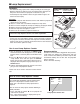
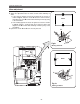
Electrical Adjustments
1. Receive the 100%whole-white computer signal with
Computer 1 [Analog RGB] mode.
2. Enter the service mode.
3. Measure luminance on the screen with the luminance
meter. It is A for the reading of luminance meter.
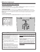
4. Change the signal source to the 50%whole-white
computer signal with Computer 1 [Analog RGB]
mode.
5. Select group no. “4”, Item no. “6” and change the Data
value to make the reading of luminance meter to be A
x 23%
.
Luminance adjustment adjustment [PC]
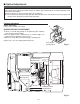
7
1. Receive the 16-step gray scale composite video sig-
nal with Video mode.
2. Enter the service mode.
3. Connect a digital voltmeter to test point “TPVRB”(+)
and chassis ground (-).
4. Select group no. “5”, Item no. “17” and adjust the volt-
age to be 1.0 ±0.05Vdc by changing the Data value.
5. Connect a digital voltmeter to test point “TPGVRT (+)
and chassis ground (-).
6. Select Item no. “18” and adjust the voltage to be 2.5
±0.05Vdc by changing the Data value.
A/D Ref. Voltage adjustment [Video]
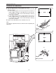
8
1. Receive the 16-step gray scale composite video sig-
nal with Video mode.
2. Enter the service mode.
3. Connect an oscilloscope to test point “TP13G”(+)
and chassis ground (-).
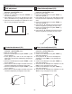
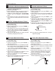
4. Select group no. “3”, Item no. “1” and adjust the ampli-
tude “a” to be 1.35 ±0.1V by changing the Data value.
* This changes all the RGB amplitude at the same
time. Item no. “2” can be adjusted for G only.
5. Connect an oscilloscope to test point “TP13B”(+)
and chassis ground (-).
6. Select Item no. “3” and adjust the amplitude “a” to be
1.35 ±0.1V by changing the Data value.
7. Connect an oscilloscope to test point “TP13R”(+)
and chassis ground (-).
8. Select Item no. “4” and adjust the amplitude “a” to be
1.35 ±0.1V by changing the Data value.
(a)
A/D Input adjustment [Video]
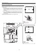
9
1. Receive the 100%whole-Black composite video sig-
nal with Video mode.
2. Enter the service mode.
3. Connect an oscilloscope to test point “TP531” (+) and
chassis ground (-).
4. Select group no. “5”, Item no. “11” and adjust the
black level to be maximum amplitude by changing the
Data value.
5. Connect an oscilloscope to test point “TP501” (+) and
chassis ground (-).
6. Select Item no. “12” and adjust the black level to be
maximum amplitude by changing the Data value.
7. Connect an oscilloscope to test point “TP561” (+) and
chassis ground (-).
8. Select Item no. “13” and adjust the black level to be
maximum amplitude by changing the Data value.
Note: This adjustment should be done after A/D Input
adjustment [Video].
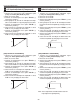
Pedestal Level
Black Level
Pedestal adjustment [Video]
10
1. Receive the 16-step gray scale video composite sig-
nal with Video mode.
2. Enter the service mode.
3. Connect an oscilloscope to test point “TP531”(+)
and chassis ground (-).
4. Select group no. “4”, Item no. “3” and adjust the white
level to be minimum amplitude by changing the Data
value.
5. Connect an oscilloscope to test point “TP501”(+)
and chassis ground (-).
6. Select Item no. “4” and adjust the white level to be
minimum amplitude by changing the Data value.
7. Connect an oscilloscope to test point “TP561”(+)
and chassis ground (-).
8. Select Item no. “5” and adjust the white level to be
minimum amplitude by changing the Data value.
(a)
White Level
Video Gain adjustment [Video]
11