
User's Manual

-11-
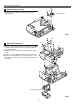
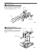
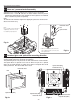
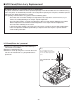
Fig.7
A
Ballast Board
FN905
Power DC
Board
A
A
AB
B
Ballast Cover
Mechanical Disassemblies
1 Remove 4 screws A (T3x8) and then pull the Ballast
Board Ass’y upward off.
2 Remove 3 screws B (T3x20) to take the Fan (FN905) off.
3 Unhook 4 hooks and take the Lamp Ballast Board off.
4 Disconnect the Power DC board from the Power AC
board.
Lamp Ballast Board removal
9
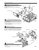
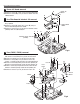
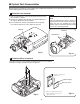
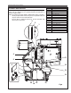
1 Remove 4 screws A (T3x20) to take the fan (FN904) off.
2 Remove 3 screws B (T4x25) to take the fan (FN907) off.
3 Remove 4 screws C (T3x10) to take the duct ass’y off.
4 Remove 2 screws D (T3x6) to take the Lens Shift Motor
and Sensor SW Holder from the Base.
Fan & Motor removal
8
Motor and
Sensor Holder
Fig.6
A
A
AA
B
B
B
C
C
C
C
D
D
B
FN904
FN907