Notice ● CORRECTION PRODUCTION CHANGE SERVICE FLASH ADD INFORMATION FILE NO. REVISION-1 Please add this notice to the Service Manual listed below. Category : Model : Multi-media Projector LC-XG110 LC-XG210 Issued Date : October / 2003 MJ7-XG11000 Effective from : Chassis No. MH7-XG21000 Destination : Canada, U.S./Europe REF. NO. : SM5110512 NOTE: Match the Chassis No. on the unit’s back cover with the Chassis No. in the Service Manual. If the Chassis. No.
Correction Page 19, Lamp Replacement Correct the following information. Amend the counter value indicated with the underline. How to check Lamp Replace Counter The LAMP REPLACEMENT indicator will illuminate when the Lamp Replace Counter reaches 1500 hours. This is to indicate that lamp replacement is required. You can check the lamp replace counter following to below procedure. 1 Press and hold the pointer e on the projector for more than 20 seconds.
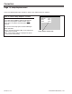
SERVICE MANUAL Multimedia Projector Model No. LC-XG110 LC-XG210 (U.S.A., Canada, Europe) ORIGINAL VERSION Chassis No. MJ7-XG11000 MH7-XG21000 Give complete “Chassis No.” for parts order or serviceing, it is shown on the rating sheet on the cabinet on the projector. FOREWORD For your convenience, all service parts, identified in this manual are available through Eiki’s normal distribution channels.
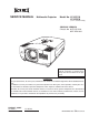
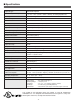
■ Contents ■ Safety Instructions ________________________________________________3 ■ Specifications ____________________________________________________4 ■ Adjustments after Parts Replacement ________________________________5 ■ Circuit Protections ________________________________________________6 Fuse ______________________________________________________6 Thermal switch ______________________________________________6 Interlock switch ______________________________________________6 Warning temperature and p
■ Safety Instructions SAFETY PRECAUTIONS WARNING: The chassis of this projector is isolated (COLD) from AC line by using the converter transformer. Primary side of the converter and lamp power supply unit circuit is connected to the AC line and it is hot, which hot circuit is identified with the line ( ) in the schematic diagram. For continued product safety and protection of personnel injury, servicing should be made with qualified personnel. The following precautions must be observed.
■ Specifications Projector Type Multi-media Projector Dimensions (W x H x D) 11.9" x 6.4" x 16.6" (302mm x 162mm x 422mm) (not including Adjustable Feet) Net Weight 17.2 lbs (7.8 kg) LCD Panel System 0.99” TFT Active Matrix type, 3 panels Panel Resolution 1024 x 768 dots Number of Pixels 2,359,296 (1024 x 768 x 3 panels) Color System PAL, SECAM, NTSC, NTSC4.43, PAL-M and PAL-N High Definition TV SIgnals 480i, 480p, 575i, 575p, 720p. 1035i and 1080i Scanning Frequency H-sync.
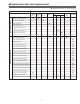
■ Adjustments after Parts Replacement ● : Adjustment necessary ❍ : Check necessary Optical Adjustments Disassembly / Replaced Parts LCD/ Prism Ass’y Condenser Lens Condenser lens adjustment ❍ ● Relay lens adjustment ❍ Relay Lens R G B Power DC Board Main Board ● ● Mirror adjustment Contrast Adjustment ● R-Contrast adjustment ● G-Contrast adjustment ● B-Contrast adjustment ● Fan voltage adjustment Electrical Adjustments Polarized glass Mirror Video center adjustment ● NRS adjustm
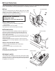
■ Circuit Protections This projector provides the following circuit protections to operate in safety. If the abnormality occurs inside the projector, it will automatically turn off by operating one of the following protection circuits. ● Fuse Fuse Line Filter Board The fuse is located inside of the projector. When either the LAMP indicator or the READY indicator is not illuminated, fuse may be opened. Check the fuse as following steps. It should be used the specified fuse as follows; FUSE PART NO.
Circuit Protections ● Warning temperature and power failure protection The projector will be automatically turned off when the internal temperature of the projector exceeds the normal operating temperature, or the cooling fans stops, or the power supplies in the projector are failed. - If the TEMP WARNING indicator (red) is flashing, it may detect the abnormal temperature inside the projector.
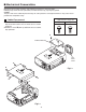
■ Mechanical Disassemblies Mechanical disassemble should be made following procedures in numerical order. Following steps show the basic procedures, therefore unnecessary step may be ignored. Caution: The parts and screws should be placed exactly the same position as the original otherwise it may cause loss of performance and product safety.
Mechanical Disassemblies 2 Main Board & Thermal-SW removal B 1 Remove 1 screw A (M3x8) to take the thermal SW905 switch(SW905). 2 Remove 5 screws B (M3x6) to take the Main Board upward. Main Board B B AV Board B E COM Board Rear Panel Ass’y A B D D D D E 3 AV, COM Board & Rear Panel removal 1 Remove 1 screw C (M4x10) and take the Rear Panel Fig.2 ass’y upward off. 2 Remove 4 screws D (T3x6) to take the AV Board from the Rear Panel ass’y off.
Mechanical Disassemblies A 6 Speaker base removal A 1 Remove 3 screws A (T3x10) and then remove the A Speaker Base Speaker Base. Fig.4 D E 7 Optical Unit removal D E C E 1 Loosen 1 screw A on the lamp cover and 2 screws B on the lamp house and the take the Lamp House off from the cabinet bottom. 2 Remove 2 screws C (M3x8) and disconnect the lamp socket. 3 Remove 2 screws D (M3x8) and remove sheild plate.
Mechanical Disassemblies 8 Fan & Motor removal 1 Remove 4 screws A (T3x20) to take the fan (FN904) off. 2 Remove 3 screws B (T4x25) to take the fan (FN907) off. 3 Remove 4 screws C (T3x10) to take the duct ass’y off. 4 Remove 2 screws D (T3x6) to take the Lens Shift Motor FN904 and Sensor SW Holder from the Base. A A A A FN907 D C D C B Motor and Sensor Holder C C B Fig.6 B 9 Lamp Ballast Board removal 1 Remove 4 screws A (T3x8) and then pull the Ballast Board Ass’y upward off.
Mechanical Disassemblies 10 Power AC Board removal A 1 Remove 4 screws A ( T3x6) to take the Power Board off. 2 Remove 4 screws B (T3x10) to take the Holder from the cabinet bottom. Power AC Board A A A 11 Line Filter Board & Interlock SW removal B B 1 Remove 3 screws C (T3x10) to take the Filter Board Ass’y upward. B 2 Remove 3 screws D (T3x8) and 1 screw E (T3x6) to Power Board Holder take the Filter Board from the Holder.
■ Optical Parts Disassemblies Before taking this procedure, remove Cabinet Top and Main Board following to the “Mechanical Disassemblies”. Disassembly requires a 2.0mm hex wrench. 1 Projection Lens removal 1 Shift the projection lens to the end of top position by pressing the Lens Shift (+) button. 2 Remove the Cabinet Front-Top and Lens Holder following to the chapter “Mechanical Disassemblies”.
Optical Pats Disassemblies 3-1 Prism ass’y removal and disassembly 1 Remove 4 hex screws A and take the LCD/Prism ass’y off upward. 2 Remove each 1 screw B and take the Glass Holder, and then pull the Optical filter, Polarized Glass-Out upwards off. These glasses are mounted for R, G and B LCD panels respectively. Note: To avoid the CG and focus alignments slipping off, please be careful to handle the LCD/Prism ass'y.
Optical Parts Disassemblies 4 Relay Lens disassembly 1 Remove 2 hex screws A and pull the Relay Lens ass’y upward. 2 Remove 2 screws B to take the Lens off from the holder. Note: There is no mounting direction of the lens. A A Holder B B Relay Lens Fig.4-2 Fig.4-1 5 Integrator-In disassembly 1 Remove 2 hex screws A and take the Integrator Lens ass’y. 2 Remove 2 screws B to take the Lens off from the holder. A A * Lens should be placed as the flat surface side comes to the holder side.
6 Condenser Lens disassembly 1 Remove 2 hex screws A and take the Condenser Lens ass’y. 2 Remove 4 screws B to take the Lens off from the holder. A A * Lens should be placed as the flat surface side comes to the holder side. B B Holder B Condenser Lens B Fig.6-1 Fig.6-2 7 Optical Unit Top removal 1 Loosen 2 screws A on the holder on the optical unit. 2 Remove 7 screws B to take the Optical Unit Top off upward.
Optical Parts Disassemblies Key No. Locations and Directions 1 2 3 4 5 6 7 8 9 10 11 12 13 14 15 16 When the optical parts in the optical unit mounting or assembling, the parts must be mounted in the specified location and direction as shown in figure below. Note: The arrow in the figure below is indicated that there is the direction of part placement. Place each part as the printed marker on the part comes to each arrow direction. The key No.
■ LCD Panel/Prism Ass’y Replacement IMPORTANT NOTICE on LCD Panel/Prism Ass'y Replacement LCD panels used for this model can not be replaced separately. Do not disassemble the LCD Panel/Prism Ass’y. These LCD panels are installed with precision at the factory. When replacing the LCD panel, should be replaced whole of the LCD panels and prism ass’y at once. After replacing LCD Panel/Prism ass’y, please check the following points.
■ Lamp Replacement WARNING: ORDER REPLACEMENT LAMP Type No. Service Parts No. POA-LMP59 610 305 5602 - For continued safety, replace with a lamp assembly of the same type. - Allow the projector to cool for at least 45 minutes before you open the lamp cover. The inside of the projector can become very hot. - Do not drop the lamp module or touch the glass bulb! The glass can shatter and cause injury. Screws Procedure 1 Turn off the projector and disconnect the AC cord.
■ Optical Adjustments Before taking optical adjustments below, remove the Cabinet Top and Main Board, if required, following to the “Mechanical Disassemblies” Adjustments require a 2.0mm hex wrench and a slot screwdriver. Note: Do not disconnect connectors K8E, K8F, K8G, K8J and K8K on the main board, because the projector can not turn on due to operate the power failure protection. Contrast adjustment [Before Adjustment] - Input a 100% of black raster signal.
Optical Adjustments Condenser Lens adjustment 1 Turn the projector on by a state of without FPC cables. 2 Adjust the adjustment base of condenser lens ass’y to make color 3 uniformity in white. 1) If the shading appears on the left or right of the screen as shown in Fig.2-1, loosen 2 screws A with the 2.0mm hex driver, and adjust the slot B to make color uniformity in white by using a slot screwdriver. 2) If the shading appears on the top or bottom of the screen as shown in Fig.
Optical Adjustments Relay Lens-Out adjustment 1 Turn the projector on by a state of without FPC cables. 2 Adjust the adjustment base of relay lens ass’y to make color uniformity in white. 1) If the shading appears on the left or right of the screen as shown in Fig.3-1, loosen 2 screws A with the 2.0mm hex driver, and adjust the slot B to make color uniformity in white by using a slot screwdriver. 2) If the shading appears on the top or bottom of the screen as shown in Fig.3-2, loosen 2 screws C with the 2.
Optical Adjustments Mirror adjustment 1 Turn the projector on by a state of without FPC cables. 2 Adjust the adjustment base of mirror to make color uniformity in white. 1) If the cyan bar appears on the top or bottom of the screen as shown in Fig.4-1, loosen 2 screws A with the 2.0mm hex driver, and adjust the screw B to make color uniformity in white by using a slot screwdriver. 2) If the shading appears on the left or right of the screen as shown in Fig.4-2, loosen 2 screws C with the 2.
■ Electrical Adjustments ● Service Adjustment Menu Operation To enter the service mode To enter the “Service Mode”, press and hold the MENU and IMAGE button on the projector at the same time for more than 3 seconds. The service menu appears on the screen as follows. To adjust service data Select the adjustment group no. (Group) by pressing the MENU(+) button or IMAGE(-) button, and select the adjustment item no. (No.
Electrical Adjustments ● Circuit Adjustments CAUTION: The each circuit has been made by the fine adjustment at factory. Do not attempt to adjust the following adjustments except requiring the readjustments in servicing otherwise it may cause loss of performance and product safety. [Adjustment Condition] ● Input signal Video signal .......................... 1.0Vp-p/75Ω terminated, 16 steps gray scale (Composite video signal) Computer signal .................... 0.
Electrical Adjustments 3 NRS adjustment 5 Video Gain adjustment [PC] 1. Receive the 16-step gray scale computer signal with Computer 1 [Analog RGB] mode. 2. Enter the service mode. 3. Connect an oscilloscope to test point “TP2531” (+) and chassis ground (-). 4. Select group no. “5”, Item no. “7” and adjust the amplitude “a” to be 2.0 ±0.1V by changing the Data value. 5. Select Item no. “6” and adjust the amplitude “b” to be 7.1 ±0.1V by changing the Data value. (b) (a) 1.
Electrical Adjustments 7 Luminance adjustment adjustment [PC] 1. Receive the 100%whole-white computer signal with Computer 1 [Analog RGB] mode. 2. Enter the service mode. 3. Measure luminance on the screen with the luminance meter. It is A for the reading of luminance meter. 4. Change the signal source to the 50%whole-white computer signal with Computer 1 [Analog RGB] mode. 5. Select group no. “4”, Item no. “6” and change the Data value to make the reading of luminance meter to be A x 23%. 8 A/D Ref.
Electrical Adjustments 12 A/D Input adjustment [Component] 13 Pedestal adjustment [Component] [1080i-A/D INPUT ADJUSTMENT] 1. Receive the 16-step gray scale component signal [1080i] with Video [Y/Pb,Pr/Cb,Cr] mode. 2. Enter the service mode. 3. Connect an oscilloscope to test point “TP13G” (+) and chassis ground (-). 4. Select group no. “3”, Item no. “1” and adjust the amplitude “a” to be 1.35 ±0.1V by changing the Data value. 5. Connect an oscilloscope to test point “TP13B” (+) and chassis ground (-).
Electrical Adjustments 14 Video Gain adjustment [Component] 17 White Balance adjustment 1. Receive the 16-step gray scale component signal [1080i] with Video [Y/Pb,Pr/Cb,Cr] mode. 2. Enter the service mode. 3. Connect an oscilloscope to test point “TP531” (+) and chassis ground (-). 4. Select group no. “4”, Item no. “3” and adjust the white level to be minimum amplitude by changing the Data value. 5. Connect an oscilloscope to test point “TP501” (+) and chassis ground (-). 6. Select Item no.
Electrical Adjustments Test Points and Locations ● MAIN BOARD K8L TP2561 K8E K25R K25B K8M K8R TP501 K8G K8F TP561 TPFAN1 TP13B TP2531 K25G TP13G TP13R IC401 TPDVS TPDHS TPGVRT TP531 TPVRB IC9401 IC3201 IC4101 K8P K8Q TPHAFC K8J TPFAN2 TPFAN3 IC1801 TP351 IC801 TPHD TPGHS TPVD TPGVS IC341 IC6361 K8T IC201 IC1101 TPHS TPVS TP21G TP21B K8W -30- TP20G TP20B TP21R TP20R K8S K8V K8X
Electrical Adjustments ● Service Adjustment Data Table No. Adjustment Item Group: 0 TA1318 0 SEP_LEV 1 HD_PHASE 2 V_FREQ 3 H_FREQ 4 HD_IN Group: 1 uPD64083 0 NRMD 1 HDP 2 CDL 3 DYCOR 4 DYGAIN 5 DCCOR 6 DCGAIN 7 VAPGAIN 8 VAPINV 9 YPFT 10 YPFG 11 V1PSEL 12 VEGSEL 13 CC3N 14 SELD2FH 15 SELD1FL 16 YHCOR 17 HPLLFG 18 PLLFS 19 KILR 20 HSSL 21 VSSL 22 BGPS 23 BGPW Group: 2 TB1274 0 TINT 1 SHP_EQ 2 SHP_FO 3 SHP_GAIN 4 Y_OUT_LEVEL 0.7V 5 C_OUT_LEVEL 0.
Electrical Adjustments No.
Electrical Adjustments No.
Electrical Adjustments No.
Electrical Adjustments No.
Electrical Adjustments No.
Electrical Adjustments No.
Electrical Adjustments No.
DVI-I PC1 INPUT PC2 INPUT D-SUB D-SUB MONITOR OUTPUT -39- R/C USB IC031 AUDIO-AMP.
D-SUB D-SUB PC1 MONITOR OUTPUT -40- IC1141 C 9 12 5 IC3101 VIDEO DECODER IC1141 NT/PAL-SW PAL 3L-Y/C SEP.
-41- IC304 CONTROL MEMORY <24LC168> 8 7 REF CENT RGT IC1531 D/A DRSH IC561 B-D/A S&H IC531 G-D/A S&H IC1501 D/A DWN ENBX NRG RGT NRS TP561 3 22 3 22 G B IC2561 NRS R IC2531 NRS 29, 30 IICSCL/SDA IC3561 B-LEVEL SHIFT PW_SDA PW_SCL IC351 FLASH ROM A2-A19 D0-D15 DVS IC341 S-RAM TPDVS DHS DGSH TP531 IC3531 G-LEVEL SHIFT A1-A15 D0-D15 244 TPDHS IC9401 DIGITAL BRIGHTER 323 BAOUT GAOUT BAO
Chassis Block Diagrams Audio signal processing circuit 1-4 AV BOARD K10W 10 R 12 L 5 R 14 13 Q5001 L 3 7 1 Q5002 3 R 1 Q013 Q014 18 5 L Q011 3 3 R 2,6 VOLUME SP901 8 17 Q031 EXT. SP OUT 13 K55C 1 IC031 AUDIO OUTPUT L IC001 AUDIO-AMP.
Chassis Block Diagrams Motor driving circuit FOCUS 4,5 IC801 CPU K55B IICSCL 5 5 IICSDA 4 4 30 2 3 IC5581 I/O EXPANDER (MOTER DIRIVE) K8G 29 4,5 Input Output 5 H L H L L H H L 7 1 7 2 6,7 4,5 IC5531 ZOOM DRIVE 1 3 7 4 M LENS SHIFT 9,10 18,20 IC5561 LENS SHIFT DRIVE 9 1 5 2 M BRIGHT 4,5 IC6501 BRIGHT DRIVE 1 K55E 7 1 2 Logic Table of Drive ICs (IC5561) Operation Input 1 L H H L L L Open Open M K55G AUDIO BOARD Logic Tab
IC801 CPU -44- 143 R_C P-FAIL SCL3 SDA3 SDA2 SCL2 IICSDA 13 14 15 OPTION RESISTORS FAN_DRIVE Power Fail: L 5 6 FAN_CONT3 FAN_CONT2 FAN_CONT1 Power-On: H To the ICs, controlled by IIC bus. From the power fail detection diodes.
AC CORD -45- IC801 CPU 52 51 125 SDA2 SCL2 P-FAIL MAIN BOARD Power Fail: L Q1561 IC1561 IC3103 IC3102 D1571 D6381 D451 1 2 IC1871 TEMP. SENSOR IC1571 IC6381 IC451 9V 16V 15AUDIO 5 8 11 5 8 11 D031 IC3253 IC3252 IC243 IC242 IC241 IC1102 IC3251 K8G D3253 D3252 3.3V_AD3 3.3V_AD2 3.3V_AD1 3.3_AV D3251 14.5V SDA2 SCL2 D243 D242 D241 D3103 1 1 2 2 9 9 K8A 1 2 IC1873 TEMP. SENSOR SDA2 K8K S3.
■ Troubleshooting No Power The possible causes of No Power are listed below. Please check following and refer to the chapter “Power supply and protection circuit” in the Chassis Block Diagrams on the previous page. - The abnormality on the lamp ballast board was detected. The lamp ballast board outputs error signal (LAMP_DET) to pin 123 of IC801. LAMP_DET .............. High in abnormal 1. It does not operate the power supply circuit due to detection of abnormality.
Troubleshooting No Picture The possible causes of No Picture are listed below. Please check following and refer to the chapter “Inputs & video signal processing stage”, “LCD panel driving stage” in the Chassis Block Diagrams on the previous page. 1. No picture from Video source Composite Video Input Check that the composite video signal is observed at the following points; Pin 16 of K8D, pins 4, 3 of IC141, pin 4 of IC1141, pin 88 of IC1101 (NTSC), pin 7 of IC2101 (PAL) on the Main Board.
Troubleshooting No Sound Please check following and refer to the chapter “Audio signal processing circuit” in the Chassis Block Diagrams on the previous page. 1. No audio signals at AV input circuit. Check audio signals at pins 1, 12 (Computer1), 5, 14 (Computer2) and 2, 15 (Video) of IC5001 on AV Board. Check IC5001 and peripheral circuits. 2. Incorrect operation of Input mode switching. Check AU_SW1 and AU_SW2 switching signals at pins 9 and 10 of IC5001 on the AV board.
■ Control Port Functions ● System Control & I/O Port Table (IC801) No.
Control Port Functions No.
Control Port Functions ● Parallel I/O Expander (IC1801, M66500FP) No.
Control Port Functions ● IIC Bus I/O Expander (IC5581, M62320FP) Port Functions Pin No.
Control Port Functions ● IIC Bus DA Converter (IC1531, M62399FP) Port Functions No. Name Function Name Function 1 2 3 4 5 6 7 8 9 10 11 12 13 14 15 16 17 18 19 20 R SCL SDA A05 A06 A07 A08 VrefL VrefU1 Vss VrefU2 A01 A02 A03 A04 Vcc Vdd CS2 CS1 CS0 Reset input IIC BUS SCL IIC BUS SDA not use REF_B REF_G REF_R DAC lower reference voltage input DAC upper reference voltage input(CH5~CH8) GND DAC upper reference voltage input(CH1~CH4) B_CENT G_CENT R_CENT not use Buffer power supply(2.
■ Waveform VIDEO-IN Y-IN C-IN VIDEO_Y VIDEO_CB VIDEO_CR AV_HSYNC AV_VSYNC AV_R-OUT AV_G-OUT AV_B-OUT HD_OUT VD_OUT GHS_PW -54-
Waveform GVS_PW DHS DVS B-S&H OUT G-S&H OUT R-S&H OUT NRS-G NRS-B/R -55-
■ Cleaning After long periods of use, dust and other particles will accumulate on the LCD panel, prism, mirror, polarized glass, lens, etc., causing the picture to darken or color to blur. If this occurs, clean the inside of optical unit. Remove dust and other particles using air spray. If dirt cannot be removed by air spray, disassemble and clean the optical unit. Cleaning with air spray Disassembly Cleaning 1. Remove the cabinet top following to “Mechanical Disassemblies”. 2.
■ IC Block Diagrams ● AD8185ARU ● AD9888KS140 -57-
IC Block Diagrams ● BA6287F ● BA6920F -58-
IC Block Diagrams ● BA7078AF
IC Block Diagrams ● DB7600
IC Block Diagrams ● ICS1523M ● L306070D -61-
IC Block Diagrams ● M62392 ● M62393 -62-
IC Block Diagrams ● M62399 ● ML60851 -63-
IC Block Diagrams ● PW365 ● TA1318AF
IC Block Diagrams ● TB1274AF
IC Block Diagrams ● TDA1517ATW
■ Electrical Parts List MJ7-XG11000, MH7-XG21000 Product safety should be considered when a component replacement is made in any area of a projector. Components indicated by a ! mark in this parts list and the circuit diagram show components whose value have special significance to product safety. It is particularly recommended that only parts specified on the following parts list be used for components replacement pointed out by the mark.
MJ7-XG11000, MH7-XG21000 Electrical Parts List Note: Parts order must contain Chassis No., Part No., and Descriptions.
MJ7-XG11000, MH7-XG21000 Electrical Parts List Key No. Part No. Description Key No. ASSEMBLIED BOARDS !610 308 1724 !610 301 1950 !610 302 6435 !610 303 4799 !610 304 9502 !610 306 0279 !610 303 4812 ASSY,PWB,MAIN MH7A ASSY,PWB,TEMP.SENSOR MC3A ASSY,PWB,AUDIO MC3A ASSY,PWB,A/V MC3B ASSY,PWB,R/C FRONT MC3B ASSY,PWB,COM.
MJ7-XG11000, MH7-XG21000 Electrical Parts List Key No. Q1151 Q1161 Q1163 Q141 Q142 Q143 Q144 Part No.
MJ7-XG11000, MH7-XG21000 Electrical Parts List Key No. Q2102 Q2501 Q2502 Q2511 Q2541 Q2571 Q2591 Q271 Q3103 Part No.
MJ7-XG11000, MH7-XG21000 Electrical Parts List Key No. Q3173 Q3181 Q3182 Q3301 Q3302 Q4181 Q4182 Q4801 Part No.
MJ7-XG11000, MH7-XG21000 Electrical Parts List Key No. Q5132 Q5168 Q6141 Q6142 Q6146 Q6161 Q6166 Q6171 Part No.
MJ7-XG11000, MH7-XG21000 Electrical Parts List Key No. IC3252 IC3253 IC3291 IC341 IC3501 IC351 IC3531 IC3561 IC361 IC362 IC391 IC392 IC401 IC4101 IC4201 IC4231 IC4251 IC4261 IC4271 IC4281 IC451 IC4801 IC4811 IC4821 IC4831 IC4881 IC4891 IC501 IC5131 IC5191 IC531 IC561 IC6101 IC6111 IC6121 IC6131 IC6161 IC6181 IC6182 IC6301 IC6321 IC6341 IC6361 IC6381 IC8001 IC8003 IC8004 IC801 IC802 IC803 IC804 IC8041 IC805 IC8051 IC8061 IC8071 IC808 IC8081 IC8091 Part No.
MJ7-XG11000, MH7-XG21000 Electrical Parts List Key No. Part No.
MJ7-XG11000, MH7-XG21000 Electrical Parts List Key No. Part No.
MJ7-XG11000, MH7-XG21000 Electrical Parts List Key No. Part No.
MJ7-XG11000, MH7-XG21000 Electrical Parts List Key No. Part No.
MJ7-XG11000, MH7-XG21000 Electrical Parts List Key No. Part No.
MJ7-XG11000, MH7-XG21000 Electrical Parts List Key No. Part No.
MJ7-XG11000, MH7-XG21000 Electrical Parts List Key No. Part No.
MJ7-XG11000, MH7-XG21000 Electrical Parts List Key No. Part No.
MJ7-XG11000, MH7-XG21000 Electrical Parts List Key No. Part No.
MJ7-XG11000, MH7-XG21000 Electrical Parts List Key No. Part No.
MJ7-XG11000, MH7-XG21000 Electrical Parts List Key No. Part No.
MJ7-XG11000, MH7-XG21000 Electrical Parts List Key No. Part No.
MJ7-XG11000, MH7-XG21000 Electrical Parts List Key No. Part No.
MJ7-XG11000, MH7-XG21000 Electrical Parts List Key No. Part No.
MJ7-XG11000, MH7-XG21000 Electrical Parts List Key No. Part No.
MJ7-XG11000, MH7-XG21000 Electrical Parts List Key No. Q2051 Q2061 Q2071 Q2081 Q3866 Q5001 Q5002 Part No.
MJ7-XG11000, MH7-XG21000 Electrical Parts List Key No. Part No.
MJ7-XG11000, MH7-XG21000 Electrical Parts List Key No. Part No.
MJ7-XG11000, MH7-XG21000 Electrical Parts List Key No. Q3031 Q3032 Q3051 Q3052 Q3053 Q3054 Q3081 Q7001 Part No.
MJ7-XG11000, MH7-XG21000 Electrical Parts List Key No. Part No.
MJ7-XG11000, MH7-XG21000 Electrical Parts List Key No. Part No.
MJ7-XG11000, MH7-XG21000 Electrical Parts List Key No. Part No. D6801 D6802 D6803 D6804 D6856 407 407 407 407 407 407 407 407 407 D6857 D6858 D6859 Description Key No.
■ Mechanical Parts List MJ7-XG11000, MH7-XG21000 Note: Parts order must contain Chassis No., Part No., and Descriptions.
MJ7-XG11000, MH7-XG21000 Mechanical Parts List ● OPTICAL PARTS S3 S3 S3 L18: For R-panel L19: For G-panel L20: For B-panel L3 S4 S4 S4 L3-a: For R-panel L3-b: For G-panel L3-c: For B-panel S4 (Polarized Glasses) L3-d: For R-panel L3-e: For G-panel L3-f: For B-panel (Optical Flters) -98-
MJ7-XG11000, MH7-XG21000 Mechanical Parts List S3 S3 L4 S5 S5 L10 -99-
MJ7-XG11000, MH7-XG21000 Mechanical Parts List S3 S3 L11 L1-b L1-a (Zoom) (Focus) L12 L1 -100-
MJ7-XG11000, MH7-XG21000 Mechanical Parts List L2 L5 L14 L22 L6 L9 L23 L16 L17 L16 L15 L7 L21 L13 L8 CAUTION: Part must be placed in specified direction when replacing the optical parts. Please see “Optical Parts Disassemblies” for further instructions.
MJ7-XG11000, MH7-XG21000 Mechanical Parts List Key No. Part No. Description Key No. CABINET PARTS 1 1-a 1-b 1-c 1-d 2 3 4 5 6 7 8 9 10 11 12 13 14 15 16 17 18 19 20 22 23 21 24 25 26 27 28 610 303 8902 ASSY,BUTTON-MC3B (Including Key No.
MJ7-XG11000, MH7-XG21000 Mechanical Parts List -103-
A-key to better communications U.S.A. Canada EIKI International, Inc. 26794 Vista Terrace Drive Lake Forest, CA, USA 92630-8113 Tel : 800-242-3454 (949-457-0200) Fax : 800-457-3454 (949-457-7878) E-Mail : usa@eiki.com EIKI CANADA - Eiki International, Inc. (310 First Street - Unit 2) P.O. Box 156, Midland, ON, Canada L4R 4K8 Tel : 800-563-3454 (705-527-4084) Fax : 800-567-4069 (705-527-4087) E-Mail : canada@eiki.