MULTIMEDIA PROJECTOR MODEL LC-XE10 OWNER'S INSTRUCTION MANUAL
Table of Contents Table of Contents 2 To the Owner 3 Safety Instructions 4 Installing the Projector in Proper Position Air Circulation Moving the Projector 5 5 5 Compliance 6 Connecting the AC Power Cord 7 Features and Design 8 Part Names and Functions 9 Front Back Bottom Terminal Top Remote Control Laser Pointer Function Pointer Function Remote Control Code Wireless Mouse Operation Remote Control Operating Range Remote Control Batteries Installation 9 9 9 10 11 12 13 13 14 14 15 15 Instal
To the Owner Before operating this projector, read this manual thoroughly and operate the projector properly. This projector provides many convenient features and functions. Operating the projector properly enables you to manage those features and maintains it in better condition for a considerable time. Improper operation may result in not only shortening the product-life, but also malfunctions, fire hazard, or other accidents.
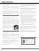
Safety Instructions All the safety and operating instructions should be read before the product is operated. Read all of the instructions given here and retain them for later use. Unplug this projector from AC power supply before cleaning. Do not use liquid or aerosol cleaners. Use a damp cloth for cleaning. This projector should be operated only from the type of power source indicated on the marking label.
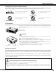
Safety Instructions Installing the Projector in Proper Position Install the projector properly. Improper installation may reduce the lamp lifetime and cause a fire hazard. 20˚ Do not put the projector on either side to project an image. Do not tilt the projector more than 20 degrees above and below. 20˚ NO SIDEWAYS Do not point the projector down to project an image. NO DOWNWARD Do not point the projector up to project an image.
Compliance Federal Communication Commission Notice Note : This equipment has been tested and found to comply with the limits for a Class B digital device, pursuant to part 15 of the FCC Rules. These limits are designed to provide reasonable protection against harmful interference in a residential installation. This equipment generates, uses and can radiate radio frequency energy and, if not installed and used in accordance with the instructions, may cause harmful interference to radio communications.
Compliance Connecting the AC Power Cord This projector uses nominal input voltages of 100-120 V or 200-240 V AC. This projector automatically selects the correct input voltage. It is designed to work with single-phase power systems having a grounded neutral conductor. To reduce risk of electrical shock, do not plug into any other type of power system. Consult your authorized dealer or service station if you are not sure of the type of power being supplied.
Features and Design This Multimedia Projector is designed with the most advanced technology for portability, durability, and ease of use. This projector utilizes built-in multimedia features, a palette of 16.77 million colors, and matrix liquid crystal display (LCD) technology. ◆ Compact Design This projector is extremely compact in size and weight. It is designed to be carried and work anywhere you wish to use.
Part Names and Functions Front t q Infrared Remote Receiver w Auto Set Up Sensor y Read screen condition in Auto Set Up operation. Do not cover or dirt this sensor face. See page 21. e r t y u q w Lens Cover (See page 56 for attaching.) Projection Lens Top Controls and Indicators Lamp Cover Exhaust Vent CAUTION Hot air is exhausted from the exhaust vent. Do not put heat-sensitive objects near this side.
Part Names and Functions Terminal q w e COMPUTER IN 2 / MONITOR OUT COMPUTER IN 1 DVI - I SERVICE PORT MCI r * S - VIDEO t R - AUDIO IN - L (MONO) VIDEO / Y – Pb/Cb – Pr/Cr AUDIO IN 1 AUDIO IN 2 AUDIO OUT USB USB RESET (VARIABLE) Do not press this button. This button is used for optional accessories. q COMPUTER IN 1 DVI-I Connect computer output (Digital/Analog DVI-I type) or Multi Card Director (optional) to this terminal.
Part Names and Functions Top This projector has control buttons and indicators on its top. q w y e u i r t o q POWER ON–OFF button Turns the projector on or off. (p19) w AUTO SET UP button Operate AUTO SET UP function. (p21) e ZOOM/FOCUS button Select ZOOM or FOCUS function. (p20) r t y u !0 !1 !2 i LAMP REPLACE indicator Turns yellow when the life of the projection lamp draws to an end.
Part Names and Functions Remote Control q q L-CLICK button Acts as left click for wireless mouse operation. (p14) w SIGNAL EMISSION indicator This indicator lights red while the laser beam is being emitted from the laser light window or a signal is being sent from the remote control to the projector. e AUTO PC button Operates the Auto PC adjustment function. (p27) r D.ZOOM buttons Selects the Digital zoom +/– mode and resize the image. (p32) t FREEZE button Freezes the projected picture.
Part Names and Functions Laser Pointer Function This remote control emits a laser beam as Laser pointer function from the laser light window. When the LASER button is pressed, laser light goes on. When the LASER button is being pressed for more than 1 minute or the LASER button is released, light goes off. The signal emission indicator lights red and laser is emitted with red light to indicate laser beam is being emitted.
Part Names and Functions Remote Control Code This projector has eight different remote control codes (Code 1-Code 8); the factory-set, initial code (Code 1) and the other seven codes (Code 2 to Code 8). This switching function prevents remote control interference when operating several projectors or video equipment at the same time. (Change the remote control code for the projector first before changing that for the remote control. See “Remote control” on page 42.
Part Names and Functions Remote Control Operating Range Point the remote control toward the projector (Infrared Remote Receiver) whenever pressing any button. Maximum operating range for the remote control is about 16.4’ (5m) and 60° in front of the projector. 16.4’ (5 m) 16.4’ (5 m) 60° 60° Remote Control Batteries Installation 1 Remove the battery compartment lid. Press the lid downward and slide it. 2 Slide the batteries into the compartment. 3 Replace the compartment lid.
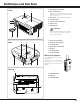
Installation Positioning the Projector This projector is designed to project on a flat projection surface and can be focused from 4.3’(1.3m) - 33.1’(10.1m). Refer to the figure and the table below for the screen size and the distance between the projector and the screen. A:B = 9:1 33.1' (10.1m) 300” (Inch Diagonal) 25.3' (7.7m) 231” 16.4' (5.0m) 10.8' (3.3m) 231” 150” 4.3' (1.3m) Min. Zoom A 178” 100” 40” Max.
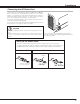
Installation Connecting to a Computer Cables used for connection (✽ = These accessories are not supplied with this projector.) • VGA Cable (HDB 15 pin) ✽ • DVI-VGA Cable (HDB 15 pin) • DVI-Digital Cable (for Single Link T.M.D.S.
Installation Connecting to Video Equipment Cables used for connection (✽ = These accessories are not supplied with this projector.) • Video Cable (RCA x 1) ✽ • Video Cable (RCA x 3) ✽ • Audio Cables (Mini Plug (stereo) x 2 or RCA x 2) ✽ • Scart-VGA Cable ✽ • S-VIDEO Cable ✽ Video Source (example) Audio Output Audio Cable (Stereo) ✽ AUDIO IN Digital Video Output S-VIDEO Output RGB Scart 21-pin Output S-VIDEO Cable ✽ ✽ COMPUTER IN 1 DVI-I Component video output equipment.
Basic Operation Turning On the Projector 1 Complete peripheral connections (with a computer, VCR, etc.) before turning on the projector. 2 Connect the projector's AC power cord into an AC outlet. The POWER indicator flashes red in a moment and turns on red. 3 Press the POWER ON-OFF button on the top control or on the remote control. The POWER indicator turns green, and the cooling fans start to operate. The preparation display appears on the screen and the count down starts.
Basic Operation Zoom Adjustment 1 2 Press ZOOM/FOCUS button on Top Control or ZOOM ▲/▼ button on Remote Control Unit. The message “Zoom” is displayed. Press ZOOM ▲ button or POINT UP button to make image larger, and press ZOOM ▼ button or POINT DOWN button to make image smaller. Zoom Message disappears after 4 seconds. Focus Adjustment 1 2 Press ZOOM/FOCUS button on Top Control or FOCUS ▲/▼ button on Remote Control Unit. The message “Focus” is displayed.
Basic Operation Keystone correction (Corner) 1 Press the Point UP/DOWN button to move the red arrow pointer to Corner and then press the SELECT button. The mark will appear on the screen. Move the projector, align the mark with the center of the desired screen and press the SELECT button. An arrow will appear on the upper left corner of the screen. 2 Use the POINT UP/DOWN/LEFT/RIGHT button to set the upper left positioning and press the SELECT button.
Basic Operation No Show Function Press the NO SHOW button on the remote control to black out the image. To restore to normal, press the NO SHOW button again or press any other button. When a projected image is captured and set as “User” in the Logo item in the Setting Menu (p40), the screen changes each time you press the NO SHOW button as follows. black out ➜ the captured image ➜ normal ➜ • • • • • The message disappears after 4 seconds. P-Timer Function Press the P-TIMER button on the remote control.
Basic Operation On-Screen Menu Remote Control ▲ 2 Move the pointer (red frame) to the Menu icon that you want to select by pressing the Point Left/Right button. ▲ Press the MENU button to display the On-Screen Menu (Menu bar). A red frame is a pointer. VOL UME+ 1 POINT button ▲ VOL UME- You can control and adjust this projector through the On-Screen Menu. Refer to the following pages to operate each adjustment on the On-Screen Menu.
Basic Operation Menu Bar For computer source Guide Window PC System Menu Image Select Menu Screen Menu Setting Menu Shows the selected Menu of the OnScreen Menu. Used to select computer system. (p26) Used to select an image level among Standard, Real, and Image 1 ~ 4. (p30) Used to adjust size of image. [Normal / True / Wide / Digital zoom +/–] (p32) Used to change settings of the projector or reset lamp replace counter.
Computer Input Input Source Selection Direct Operation Choose either Computer 1 or Computer 2 by pressing the INPUT button on the top control or press the COMPUTER 1 or COMPUTER 2 button on the remote control. Before using these buttons, correct input source should be selected through menu operation as described below.
Computer Input Computer System Selection This projector can detect most of the current computer systems with the Multi-scan system and the Auto PC adjustment function provided in the projector. When selecting computer input, the projector automatically displays the most proper image for the input signal. One of the following four displays appears on the system menu icon.
Computer Input Computer Adjustment (Auto) Auto PC Adjustment function is provided to automatically adjust Fine sync, Total dots, Horizontal, and Vertical to conform to your computer. Auto PC Adjustment function can be operated as follows. 1 Press the MENU button and the On-Screen Menu will appear. Press the Point Left/Right button to move the red frame pointer to the PC Adjust Menu icon. 2 Press the Point Down button to move the red frame pointer to the Auto PC Adj.
Computer Input Computer Adjustment (Manual) Some computers employ special signal formats which may not be tuned by Multi-scan system of this projector. This projector has Manual PC Adjustment to enable you to precisely adjust several parameters to match those signal formats. The projector has 5 independent memory areas to memorize those parameters manually adjusted. This enables you to recall the setting for a specific computer whenever you use it.
Computer Input Display area Select the resolution at the Display area dialog box. Press the SELECT button at the Display area icon and the Display area dialog box appears. Display area H Adjusts the horizontal area displayed by this projector. Press the Point Left/Right button to decrease/increase value and then press the SELECT button. Display area Display area V Adjusts the vertical area displayed by this projector.
Computer Input Image Level Selection Direct Operation Select an image level among Standard, Real, Image 1, Image 2, Image 3, and Image 4 by pressing the IMAGE button on the top control or on the remote control. IMAGE button Standard Real Standard Normal picture level preset on this projector. Image 1 Real Picture level with improved halftone for graphics. Image 2 IMAGE 1~4 User preset image in the Image Adjust Menu (p31).
Computer Input Image Level Adjustment 1 Press the MENU button and the On-Screen Menu will appear. Press the Point Left/Right button to move the red frame pointer to the Image Adjust Menu icon. 2 Press the Point Down button to move the red frame pointer to the item that you want to adjust, and then press the SELECT button. The level of each item is displayed. Adjust each level by pressing the Point Left/Right button.
Computer Input Screen Size Adjustment This projector has a picture screen resize function, which enables you to display the desirable image size. 1 Press the MENU button and the On-Screen Menu will appear. Press the Point Left/Right button to move the red frame pointer to the Screen Menu icon. 2 Press the Point Down button and move the red frame pointer to the function that you want to select and then press the SELECT button.
Video Input Input Source Selection {Video, S-Video, (Y, Pb/Cb, Pr/Cr)} Direct Operation Choose Video by pressing the INPUT button on the top control or the VIDEO button on the remote control. Before using these buttons, correct input source should be selected through menu operation as described below. INPUT button Video Computer 1 Computer 2 ✽ VIDEO button Video ✽ When Monitor out is selected at the Terminal item in the Setting Menu, Computer 2 is not displayed. See “Terminal” item on page 40.
Video Input Input Source Selection (RGB Scart 21-Pin) Direct Operation Choose Computer 2 by pressing the INPUT button on the top control or press the COMPUTER 2 button on the remote control. Before using these buttons, correct input source should be selected through menu operation as described below. INPUT button Computer 1 Computer 2 ✽ Video COMPUTER 2 button Computer 2 ✽ ✽ Computer 2 is not displayed when the COMPUTER IN 2/MONITOR OUT terminal is used as Monitor out. See “Terminal” item on page 40.
Video Input Video System Selection 1 Press the MENU button and the On-Screen Menu will appear. Press the Point Left/Right button to move the red frame pointer to the AV System Menu icon. 2 Press the Point Down button to move the red arrow pointer to the system that you want to select and then press the SELECT button. Video or S-Video Auto The projector automatically detects incoming video system, and adjusts itself to optimize its performance.
Video Input Image Level Selection Direct Operation Select an image level among Standard, Cinema, Image 1, Image 2, Image 3, and Image 4 by pressing the IMAGE button on the top control or on the remote control. IMAGE button Standard Cinema Standard Normal picture level preset on this projector. Image 1 Cinema Picture level adjusted for the picture with fine tone. Image 2 IMAGE 1~4 User preset image in the Image Adjust Menu (p37, 38).
Video Input Image Level Adjustment 1 Press the MENU button and the On-Screen Menu will appear. Press the Point Left/Right button to move the red frame pointer to the Image Adjust Menu icon. 2 Press the Point Down button to move the red frame pointer to the item that you want to adjust and then press the SELECT button. The level of each item is displayed. Adjust each level by pressing the Point Left/Right button.
Video Input Reset Resets all adjustment to their previous figure. Store To store the adjustment data, move the red frame pointer to the Store icon and press the SELECT button. The Image Level Menu will appear. Move the red frame pointer to the Image Level 1 to 4 and then press the SELECT button. Image Level Menu Move the red frame pointer to an image icon to be set and then press the SELECT button. Quit Closes the Image Adjust Menu.
Setting Setting 1 Press the MENU button and the On-Screen Menu will appear. Press the Point Left/Right button to move the red frame pointer to the Setting Menu icon. 2 Press the Point Down button to move the red frame pointer to the item that you want to set and then press the SELECT button. The Setting dialog box appears. Setting Menu (Language) Set the red frame pointer to the item and press the SELECT button.
Setting Logo Capture This function decides what to be displayed when starting up. User ···· the image you captured Default ···· the factory-set logo Off ···· count-down only Capture This function is used to capture the image being projected and use it for a starting-up display or interval of presentations. After capturing the projected image, go to the Logo function and set it as “User”. Then the captured image will be displayed when turning on the projector next time or pressing the NO SHOW button.
Setting Power management For reducing power consumption as well as maintaining the lamp life, the Power management function turns off the projection lamp when the input signal is interrupted and no button is pressed for 30 seconds or more. When the input signal is interrupted and no button is pressed for 30 seconds or more, the timer display with the message "No signal" appears on the screen. The count-down starts for the time to have been set. The count-down time can be set between 1 and 30 minutes.
Setting Remote control Remote control This projector provides eight different remote control codes (Code 1Code 8); the factory-set, initial code (Code 1) and the other seven codes (Code 2 to Code 8). This switching function prevents remote control interference when operating several projectors or video equipment at the same time. For example operating the projector in “Code 7”, both the projector and the remote control must be switched to “Code 7”.
Maintenance and Cleaning Warning Indicator The WARNING indicator shows the state of the function which protects the projector. Check the state of the WARNING indicator and the POWER indicator to take proper maintenance. The projector is shut down and the WARNING indicator is flashing red When the temperature inside the projector exceeds the normal temperature, the projector is automatically shut down to protect the inside of the projector.
Maintenance and Cleaning Cleaning the Air Filters Air filters prevent dust from accumulating on the surface of the optical elements inside the projector. Should the air filters become clogged with dust particles, it will reduce cooling fans’ effectiveness and may result in internal heat build up and adversely affect the life of the projector. Clean the air filters following the steps below. 1 Turn off the projector, and disconnect the AC power cord from the AC outlet.
Maintenance and Cleaning Lamp Replacement When the life of the projection lamp of this projector draws to an end, the LAMP REPLACE indicator lights yellow. If this indicator lights yellow, replace the lamp with a new one promptly. Top Control This indicator lights yellow when the life of the projection lamp draws to an end. CAUTION CAUTION Allow a projector to cool, for at least 45 minutes before you open the Lamp cover. The inside of the projector can become very hot.
Maintenance and Cleaning Lamp Replace Counter Be sure to reset the lamp replace counter after the lamp is replaced. When the lamp replace counter is reset, the LAMP REPLACE indicator stops lighting. 1 Turn the projector on, press the MENU button and the OnScreen Menu will appear. Press the Point Left/Right button to move the red frame pointer to the Setting Menu icon. 2 Press the Point Down button to move the red frame pointer to the Lamp counter reset item and then press the SELECT button.
Appendix Troubleshooting Before calling your dealer or service center for assistance, check the items below once again. – Make sure you have properly connected the projector to peripheral equipment as described in "Connecting to a Computer" and “Connecting to Video Equipment” on page17 and 18. – Make sure all equipment is connected to AC outlet and the power is turned on. – When you operate the projector with a computer and it does not project an image, restart the computer.
Appendix Problem: – Try these solutions. Computer 2 cannot be selected. – Select Computer 2 at the Terminal item in the Setting Menu. (See “Terminal” on page 40.) The Terminal item cannot be selected. – The Terminal item in the Setting Menu cannot be selected after Computer 2 is selected. Select other input source such as Computer 1 or Video with the INPUT button on the top control, the COMPUTER 1 button or the VIDEO button on the remote control so that the Terminal item can be selected.
Appendix Indicators and Projector Condition Check the indicators for projector condition. Indicators POWER WARNING LAMP REPLACE red/green red yellow Projector Condition The projector is OFF. (The AC power cord is unplugged.) • • • lights green. ✽ The projector is preparing for stand-by or the projection lamp is being cooled down. The projector cannot be turned on until cooling is completed. ✽ The projector is ready to be turned on with the POWER ON-OFF button.
Appendix Menu Tree Computer Input/Video Input Input Computer 1 RGB( Analog ) Go to System (1) RGB( PC Digital ) N/A RGB( AV HDCP ) N/A RGB Go to System (1) RGB( Scart ) N/A Auto Go to System (2) Video Go to System (2) S-Video Go to System (2) Y, Pb/Cb, Pr/Cr Go to System (3) Computer 2 Video ✽N/A - - - not applicable Computer Input System (1) MODE 1 MODE 2 SVGA 1 ---- Image Select Standard Real Image 1 Image 2 Image 3 Image 4 Image Adjust Contrast Brightness Color Temp 0 - 63 0
Appendix Computer Input/Video Input Video Input Setting System (2) Auto PAL SECAM NTSC NTSC 4.43 PAL-M PAL-N System (3) Auto 1080i 1035i 720p 575p 480p 575i 480i Image Select Image Adjust Auto Set up Standard Cinema Image 1 Image 2 Image 3 Image 4 Contrast Brightness Color Tint Color Temp Reset Store Quit Auto focus Auto Keystone Quick/Detail/Off Quick/Detail/Off Auto PC Adj.
Appendix Compatible Computer Specifications Basically this projector can accept a signal from all computers with the V, H-Frequency mentioned below and less than 140 MHz of Dot Clock.
Appendix Technical Specifications Projector Type Dimensions (W x H x D) Net Weight LCD Panel System Panel Resolution Number of Pixels Color System High Definition TV Signal Scanning Frequency Projection Image size (Diagonal) Projection Lens Throw Distance Projection Lamp Video Input Jacks Audio Input Jacks Computer Input 1 Terminal Computer Input 2 / Monitor Output Terminal Computer Audio Input Jacks (1 and 2) Service Port Connector USB Connector Audio Output Jack Internal Audio Amp Built-in Speaker Feet Ad
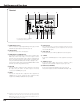
Appendix Configurations of Terminals COMPUTER INPUT/MONITOR OUTPUT TERMINAL (ANALOG) Terminal : HDB15-PIN Pin Configuration 4 5 10 15 14 2 3 9 8 13 1 7 12 1 2 3 4 5 6 7 8 6 11 Red Input Green Input Blue Input Sense 2 Ground (Horiz.sync.) Ground (Red) Ground (Green) Ground (Blue) 9 10 11 12 13 14 15 +5V Power Ground (Vert.sync.) Sense 0 DDC Data Horiz. sync. Vert. sync.
Appendix SERVICE PORT CONNECTOR Terminal : Mini DIN 8-PIN Pin Configuration 8 5 7 6 4 3 2 1 1 2 3 4 5 6 7 8 PS/2 ----CLK DATA GND --------GND ----- 1 2 3 4 Vcc - Data + Data Ground 1 2 3 4 Vcc - Data + Data Ground Serial RXD --------GND RTS / CTS TXD GND GND ADB ----ADB ----GND ------------GND USB CONNECTOR (Series A) Pin Configuration 1 2 4 3 USB CONNECTOR (Series B) Pin Configuration 2 1 3 4 Optional Parts The parts listed below are optionally supplied.
Appendix Attaching the Lens Cover When moving this projector or when it is not used for an extended period, replace the lens cover. 1 Thread the string through the hole on the lens cover and then tie a knot in the string to secure it in place. 2 Thread the other end of the string through the hole at the bottom of the projector. Then pass the lens cover through the resulting loop of the string. Tie a knot in the string to secure it in place.
Appendix USB Key Lock Function (This is optional function. Optionally supplied USB Key needed.) By using optionally supplied Projector USB Key, operation of the projector can be restricted by the projector owner. Once the projector is locked with the USB Key, only the owner who has key can operate the projector. Key registration Before using the USB key, you must register USB key into the projector. Turn the projector ON and connect the USB Key to the USB terminal located on the rear of the projector.
Appendix 58
Appendix 59
A-key to better communications U.S.A. Canada EIKI International, Inc. 30251 Esperanza Rancho Santa Margarita CA 92688-2132 U.S.A. Tel : 800-242-3454 (949)-457-0200 Fax : 800-457-3454 (949)-457-7878 E-Mail : usa@eiki.com EIKI CANADA - Eiki International, Inc. P.O. Box 156, 310 First St. - Unit 2, Midland, ON, L4R 4K8, Canada Tel : 800-563-3454 (705)-527-4084 Fax : 800-567-4069 (705)-527-4087 E-Mail : canada@eiki.