MULTIMEDIA PROJECTOR MODEL LC-W4 ✽ Projection lens is optional.
TO THE OWNER Before operating this projector, read this manual thoroughly and operate the projector properly. This projector provides many convenient features and functions. Operating the projector properly enables you to manage those features and maintain it in better condition for a considerable time. Improper operation may result in not only shortening the product life, but also malfunctions, fire hazard, or other accidents.
SAFETY INSTRUCTIONS All the safety and operating instructions should be read before the product is operated. Read all of the instructions given here and retain them for later use. Unplug this projector from AC power supply before cleaning. Do not use liquid or aerosol cleaners. Use a damp cloth for cleaning. This projector should be operated only from the type of power source indicated on the marking label.
COMPLIANCES Federal Communication Commission Notice This equipment has been tested and found to comply with the limits for a Class A digital device, pursuant to Part 15 of FCC Rules. These limits are designed to provide reasonable protection against harmful interference when the equipment is operated in a commercial environment.
TABLE OF CONTENTS FEATURES AND DESIGN PREPARATION 6 7 COMPUTER INPUT SELECTING INPUT SOURCE SELECTING COMPUTER SYSTEM COMPATIBLE COMPUTER SPECIFICATIONS PC ADJUSTMENT NAME OF EACH PART OF PROJECTOR SETTING-UP PROJECTOR 7 8 CONNECTING AC POWER CORD LENS INSTALLATION POSITIONING PROJECTOR LENS SHIFT ADJUSTMENT PICTURE LEVEL AND TILT ADJUSTMENT MOVING PROJECTOR 8 9 9 9 10 10 AUTO PC ADJUSTMENT MANUAL PC ADJUSTMENT PICTURE IMAGE ADJUSTMENT IMAGE LEVEL SELECT IMAGE LEVEL ADJUSTMENT PICTURE SCREEN ADJUST
FEATURES AND DESIGN This Multimedia Projector is designed with most advanced technology for portability, durability, and ease of use. This projector utilizes built-in multimedia features, a palette of 16.77 million colors, and matrix liquid crystal display (LCD) technology. ◆ Compatibility This projector widely accepts various video and computer input signals including; ● Computers IBM-compatible or Macintosh computer up to 1600 x 1200 resolution. ● 6 Color Systems NTSC, PAL, SECAM, NTSC 4.
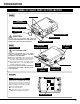
PREPARATION NAME OF EACH PART OF PROJECTOR FRONT SPEAKERS INFRARED REMOTE RECEIVER PROJECTION LENS LENS CAP (Option) CARRYING HANDLE CAUTION Do not turn on a projector with lens cap attached. High temperature from light beam may damage lens cap and result in fire hazard. BACK EXHAUST VENT EXHAUST VENT ADJUSTABLE FEET INFRARED REMOTE RECEIVER AIR INTAKE VENT HOT AIR EXHAUSTED ! Air blown from exhaust vent is hot. When using or installing a projector, following precautions should be taken.
PREPARATION SETTING-UP PROJECTOR CONNECTING AC POWER CORD This projector uses nominal input voltages of 100-120 V or 200-240 V AC. This projector automatically selects correct input voltage. It is designed to work with singlephase power systems having a grounded neutral conductor. To reduce risk of electrical shock, do not plug into any other type of power system. Consult your authorized dealer or service station if you are not sure of type of power supply being in use.
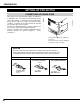
PREPARATION LENS INSTALLATION Before setting up a projector, install Projection Lens on Projector. 1. Before installation, check where a projector is used and prepare suitable lens. For specifications of a Projection Lens, refer to manual separately attached or contact sales dealer where you purchased a projector. 2. For installation, refer to installation manual supplied to a Projector. When moving or setting up a projector, be sure to replace Lens Cap to protect surface.
PREPARATION PICTURE LEVEL AND TILT ADJUSTMENT Picture tilt and projection angle can be adjusted by rotating ADJUSTABLE FEET. Projection angle can be adjusted up to 6.9 degrees by rotating Adjustable Feet. DOWN UP UP DOWN ADJUSTABLE FEET MOVING PROJECTOR Use carry handle when moving a projector. Replace lens cap and retract adjustable feet. CAUTION IN CARRYING OR TRANSPORTING A PROJECTOR ● Do not drop or bump a projector, otherwise damages or malfunctions may result.
CONNECTING PROJECTOR TERMINALS OF PROJECTOR This projector applies various input/output terminals and 3 terminal slots for expansion to tune to diversity of signals from computers and video equipment. 3-built-in Terminal Slots enable you to arrange desired combinations of input sources just by changing Terminal Boards. For Terminal Boards, contact sales dealer where you purchased a projector.
CONNECTING PROJECTOR INPUT/OUTPUT TERMINALS AND JACKS INPUT 2 INPUT 1 INPUT 1, 2, 3 DVI INPUT TERMINAL Connect component video output (Cr, Y, Cb or Pr, Y, Pb) from video equipment to R/Pr, G/Y and B/Pb jacks or connect computer output [5 BNC Type (Red, Green, Blue, Horiz. Sync and Vert. Sync.)] from computer to R/Pr, G/Y, B/Pb, H/HV and V jacks.
CONNECTING PROJECTOR SERIAL PORT OUT TERMINAL If you control a projector by computer, you must connect a cable (not provided) from your computer to this terminal. This terminal outputs signal from SERIAL PORT IN. More than two projectors can be controlled with one computer by connecting SERIAL PORT IN. of another projector to this terminal.
CONNECTING PROJECTOR CONNECTING TO COMPUTER Cables used for connection (✽ = Cables are not supplied with this projector.) • DVI-VGA Cable NOTE : • Control Cable for PS/2 port, Serial port, or ADB port When connecting cable, power cords of both a • DVI Cable projector and external equipment should be disconnected from AC outlet. Turn a projector • BNC Cable (BNC x 5) ✽ and peripheral equipment on before computer is • Audio Cables (RCA x 2) ✽ switched on.
CONNECTING PROJECTOR CONNECTING TO VIDEO EQUIPMENT Cables used for connection NOTE : When connecting cable, power cords of both a projector and external equipment should be disconnected from AC outlet. Turn a projector and peripheral equipment on before computer is switched on. • Video Cable (BNC x 1, BNC x 2 or BNC x 3) ✽ • S-VIDEO Cable ✽ • Audio Cable (RCA x 2) ✽ (✽ = Cables are not supplied with this projector.) Component video output equipment.
BEFORE OPERATION TOP CONTROLS AND INDICATORS This projector has CONTROL BUTTONS (TOP CONTROLS) and INDICATORS on its top. TOP CONTROL AND INDICATORS FOCUS BUTTONS VOLUME BUTTONS INPUT BUTTONS POWER ON–OFF BUTTON Used to adjust focus. (P22) Used to adjust volume. (P24) Used to select input source. (P25) Used to turn a projector on or off. (P21) LAMP REPLACE INDICATOR Turns to yellow when life of a projection lamp draws to an end. (P4547, 50) ZOOM BUTTONS Used to adjust zoom.
BEFORE OPERATION OPERATION OF REMOTE CONTROL LASER POINTER (Drag ON) INDICATOR Left Side POWER ON-OFF BUTTON ON Lights red while laser beam is emitted from Laser Light Window. Lights green when drag ON position. (P43) AUTO PC ON-OFF D.ZOOM FREEZE NO SHOW LOCK ALL OFF MUTE BUTTON Used to mute sound. (P24) DRAG ON/OFF BUTTON ALL-OFF SWITCH When using Remote Control Unit, turn this switch to “ON.” And turn it to “ALL OFF” when it is not used.
BEFORE OPERATION NO SHOW BUTTON D.ZOOM BUTTON Used to select DIGITAL ZOOM +/– mode and resize image. (P33) AUTO PC ON-OFF D.ZOOM FREEZE NO SHOW SELECT BUTTON LOCK Used to execute the selected item, or to expand or compress image in DIGITAL ZOOM +/- mode. (P33) Used to turn picture into black image. (P23) MUTE IMAGE VOLUME- SELECT VOLUME+ KEYSTONE MENU FREEZE BUTTON Used to freeze picture.
BEFORE OPERATION OPERATING ON-SCREEN MENU HOW TO OPERATE ON-SCREEN MENU You can control and adjust this projector through ON-SCREEN MENU. Refer to following pages to operate each adjustment on ON-SCREEN MENU. REMOTE CONTROL UNIT AUTO PC ON-OFF 1 DISPLAY MENU Press MENU button to display ON-SCREEN MENU. D.ZOOM .ZOOM FREEZE NO O SHO SHOW LOCK 2 MOVING POINTER Move pointer (✽ see below) or adjust value of item by pressing POINT button(s) on Top Control or on Remote Control Unit.
BEFORE OPERATION MENU BAR FOR PC SOURCE Press MENU BUTTON while connecting to PC input source. IMAGE SELECT MENU SCREEN MENU SETTING MENU Used to adjust size of image. [Normal /Full/True/Digital zoom +/–] (Refer to P33) Used to change settings of projector or reset Lamp Replace Counter. (Refer to P39-42) GUIDE WINDOW PC SYSTEM MENU Shows selected item of ONSCREEN MENU. Used to select computer system. (Refer to P26-28) Used to select image level among Standard, Real and Image 1 ~ 4.
BASIC OPERATION TURNING ON / OFF PROJECTOR TURNING ON PROJECTOR 1 Complete peripheral connections (with Computer, VCR, etc.) before turning on projector. (Refer to "CONNECTING TO PROJECTOR" on Pages 12~15 for connecting that equipment.) LAMP STATUS INPUT 1 1 2 3 2 Connect a projector's AC Power Cord into a wall outlet and turn MAIN ON / OFF SWITCH to ON. LAMP indicator lights RED, and READY indicator lights GREEN. Press POWER ON-OFF button on Top Control or on Remote Control Unit to ON.
BASIC OPERATION ADJUSTING SCREEN ZOOM ADJUSTMENT 1 Press ZOOM ▲/▼ button on Top Control or on Remote Control Unit. Message “Zoom” is displayed. 2 Press ZOOM ▲ button to make image larger, and press ZOOM ▼ button to make image smaller. Zoom Message disappears after 4 seconds. FOCUS ADJUSTMENT 1 Press FOCUS ▲/▼ button on Top Control or on Remote Control Unit. Message “Focus” is displayed. 2 Adjust focus of image by pressing FOCUS ▲/▼ button(s) . Focus Message disappears after 4 seconds.
BASIC OPERATION PICTURE FREEZE FUNCTION Press FREEZE button on Remote Control Unit to freeze picture on-screen. To cancel FREEZE function, press FREEZE button again or press any other button except POINT / SELECT / RIGHT CLICK / LASER button. NO SHOW FUNCTION Press NO SHOW button on Remote Control Unit to black out a image. To restore to normal, press NO SHOW button again or press any other button except POINT / SELECT / RIGHT CLICK / LASER button. No show Message disappears after 4 seconds.
BASIC OPERATION SOUND ADJUSTMENT Indicates roughly level of volume. DIRECT OPERATION Volume Press VOLUME (+/–) button(s) on Top Control or on Remote Control Unit to adjust volume. Volume dialog box appears on screen for a few seconds. (+) button to increase volume, and (–) button for decreasing. Mute Press MUTE button on Remote Control Unit to cut off sound. To restore sound to its previous level, press MUTE button again or press Volume (+/–) button(s). Press MUTE button to set Mute function On or Off.
COMPUTER INPUT SELECTING INPUT SOURCE DIRECT OPERATION Select INPUT source by pressing INPUT 1, INPUT 2 and INPUT 3 buttons on Remote Control Unit. Select INPUT source by pressing INPUT ▲/▼ button on Top Control. MENU OPERATION 1 2 INPUT ▲/▼ buttons INPUT 1 button INPUT 1 INPUT 1 INPUT 2 button INPUT 2 INPUT 2 INPUT 3 button INPUT 3 INPUT 3 Press MENU button and ON-SCREEN MENU will appear. Press POINT LEFT/RIGHT buttons to select Input and press SELECT button.
COMPUTER INPUT AUTOMATIC MULTI-SCAN SYSTEM This projector automatically tunes to most different types of computers based on VGA, SVGA, XGA, SXGA, WXGA or UXGA (refer to “COMPATIBLE COMPUTER SPECIFICATIONS” on page 27). When selecting Computer, this projector automatically tunes to incoming signal and projects proper image without any special setting. (Some computers need setting manually.) Note : Projector may display one of following messages.
COMPUTER INPUT COMPATIBLE COMPUTER SPECIFICATIONS Basically this projector can accept a signal from all computers with V, H-Frequency mentioned below and less than 230 MHz of Dot Clock.
COMPUTER INPUT When a input signal is digital from DVI terminal, refer to chart below. ON-SCREEN DISPLAY RESOLUTION H-Freq. (kHz) V-Freq. (Hz) ON-SCREEN DISPLAY RESOLUTION H-Freq. (kHz) V-Freq. (Hz) D-VGA D-SVGA D-XGA D-SXGA 1 640 x 480 800 x 600 1024 x 768 1280 x 1024 31.469 37.879 48.363 63.981 59.940 60.317 60.004 60.020 D-SXGA 2 D-SXGA 3 D-UXGA 1280 x 1024 1280 x 1024 1600 x 1200 60.276 31.65 75.00 58.069 29.8 60.00 NOTE : Specifications are subject to change without notice.
COMPUTER INPUT MANUAL PC ADJUSTMENT This projector can automatically tune to display signals from most personal computers currently distributed. However, some computers employ special signal formats which are different from standard ones and may not be tuned by Multi-Scan system of this projector. If this happens, projector cannot reproduce a proper image and image may be recognized as a flickering picture, a non-synchronized picture, a non-centered picture or a skewed picture.
COMPUTER INPUT Display area Selects area displayed with this projector. Select resolution at Display area dialog box. Press SELECT button at Display area icon and Display area dialog box appears. Display area H Display area Adjustment of horizontal area displayed with this projector. Press POINT LEFT/RIGHT button(s) to decrease/increase value and then press SELECT button. Display area V Adjustment of vertical area displayed with this projector.
COMPUTER INPUT PICTURE IMAGE ADJUSTMENT IMAGE LEVEL SELECT (DIRECT) Select image level among Standard, Real, Image 1, Image 2, Image 3 and Image 4 by pressing IMAGE button on Top Control or on Remote Control Unit. IMAGE button Standard Real Standard Normal picture level preset on this projector. Image 1 Real Picture level with improved halftone for graphics. Image 2 IMAGE 1~4 User preset picture adjustment in IMAGE ADJUST Menu (P32).
COMPUTER INPUT IMAGE LEVEL ADJUSTMENT 1 2 Press MENU button and ON-SCREEN MENU will appear. Press POINT LEFT/RIGHT buttons to move a red frame pointer to IMAGE ADJUST Menu icon. Press POINT DOWN button to move a red frame pointer to item that you want to adjust and then press SELECT button. Level of each item is displayed. Adjust each level by pressing POINT LEFT/RIGHT button(s). Contrast Press POINT LEFT button to decrease contrast, and POINT RIGHT button to increase contrast. (From 0 to 63.
COMPUTER INPUT PICTURE SCREEN ADJUSTMENT This projector has a picture screen resize function, which enables you to display desirable image size. 1 Press MENU button and ON-SCREEN MENU will appear. Press POINT LEFT/RIGHT button(s) to move a red frame pointer to SCREEN Menu icon. 2 Press POINT DOWN button and move a red frame pointer to function that you want to select and then press SELECT button. SCREEN MENU SCREEN Menu icon Move a red frame pointer to function and press SELECT button.
VIDEO INPUT SELECTING INPUT SOURCE WHEN SELECT INPUT 2 (5 BNC INPUT JACKS ) When connect component video output (Cr, Y, Cb or Pr, Y, Pb) from video equipment to R/Pr, G/Y and B/Pb jacks. 1 INPUT MENU Press MENU button and ON-SCREEN MENU will appear. Press POINT LEFT/RIGHT button to move a red frame pointer to INPUT Menu icon. 2 Press POINT DOWN button to move a red arrow pointer to Input 2 and then press SELECT button. Source Select Menu will appear.
VIDEO INPUT SELECTING VIDEO SYSTEM 1 Press MENU button and ON-SCREEN MENU will appear. Press POINT LEFT/RIGHT buttons to move a red frame pointer to AV SYSTEM Menu icon. 2 Press POINT DOWN button to move a red arrow pointer to system that you want to select and then press SELECT button. VIDEO JACK OR S-VIDEO JACK Auto Projector automatically detects incoming Video system, and adjusts itself to optimize its performance. When Video System is PAL-M or PAL-N, select system manually first.
VIDEO INPUT PICTURE IMAGE ADJUSTMENT IMAGE LEVEL SELECT (DIRECT) Select image level among Standard, Cinema, Image 1, Image 2, Image 3 and Image 4 by pressing IMAGE button on Top Control or on Remote Control Unit. IMAGE button Standard Cinema Standard Normal picture level preset on this projector. Image 1 Cinema Picture level adjusted for picture with fine tone. Image 2 IMAGE 1~4 User preset picture adjustment in IMAGE ADJUST Menu (P38).
VIDEO INPUT IMAGE LEVEL ADJUSTMENT 1 Press MENU button and ON-SCREEN MENU will appear. Press POINT LEFT/RIGHT button(s) to move a red frame pointer to IMAGE ADJUST Menu icon. 2 Press POINT DOWN button to move a red frame pointer to item that you want to adjust and then press SELECT button. Level of each item is displayed. Adjust each level by pressing POINT LEFT/RIGHT button(s). IMAGE ADJUST MENU Move a red frame pointer to item to be selected and then press SELECT button.
VIDEO INPUT 3 Store To store adjustment data, move a red frame pointer to Store icon and press SELECT button. Image Level Menu will appear. Move a red frame pointer to Image Level 1 to 4 and then press SELECT button. Image Level Menu Move a red frame pointer to image icon to be set and then press SELECT button. Other icons operates as follows. Reset Reset all adjustment to previous figure. Quit Store icon Closes IMAGE MENU.
SETTING SETTING MENU 1 Press MENU button and ON-SCREEN MENU will appear. Press POINT LEFT/RIGHT button(s) to move a red-frame pointer to SETTING icon. 2 Press POINT DOWN button to move a red-frame pointer to item that you want to set and then press SELECT button. Setting dialog box appears. SETTING MENU Set a red frame pointer to item and press SELECT button.
SETTING Power management This projector is equipped with a power management function. When the input signal is interrupted and any button is not pressed for 30 seconds or more, the power management function operates in order to reduce power consumption and conserve lamp operating time. The factory default settings for power management are "Ready" and "5 Min".
SETTING Remote control Remote control This projector has eight different remote control codes; the factoryset normal code (Code 1) and the other seven codes (Code 2 to Code 8). This switching function prevents remote control operation mixture (jam) when operating several projectors or video equipment together. For example operating projector in “Code 7,” both projector and Remote Control Unit must be switched to “Code 7.
SETTING Lamp counter reset Be sure to reset Lamp Counter when Lamp Assembly is replaced. When Lamp Replace Counter is reset, LAMP REPLACE indicator stops lighting. 1 Turn projector on, press MENU button and ON-SCREEN MENU will appear. Press POINT LEFT/RIGHT button(s) to move a red frame pointer to SETTING Menu icon. 2 Press POINT DOWN button to move a red frame pointer to “Lamp counter reset” and then press SELECT button.
APPENDIX OPERATING WIRELESS MOUSE Wireless Remote Control Unit is not only able to operate this projector but also function as a wireless mouse for most Personal Computers. POINT button, drag ON/OFF button and two CLICK buttons are used for wireless mouse operation. This Wireless Mouse function is available only when PC mouse pointer is displayed on a projected screen.
APPENDIX AIR FILTER CARE AND CLEANING Air Filter prevents dust from accumulating on a surface of Projection Lens and Projection Mirror. Should Air Filter become clogged with dust particles, it will reduce Cooling Fans' effectiveness and may result in internal heat build up and adversely affect life of projector. Clean Air Filter following steps below: 1 Turn power off, and disconnect AC power cord from an AC outlet. 2 Pull out 2 Air Filters and Air filter Covers from a projector.
APPENDIX LAMP MANAGEMENT This Projector is equipped with 2 Projection Lamps to ensure brighter image and those lamps are controlled by Lamp Management Function. Lamp Management Function detects status of two lamps and shows status on screen or on LAMP REPLACE indicator. This function also automatically controls Lamp Mode when any of lamps is out for end of life or malfunctions.
APPENDIX LAMP REPLACEMENT When the life of the Projection Lamp of this projector draws to an end, the LAMP REPLACE indicator lights yellow. If this indicator lights yellow, replace the projection lamp with a new one promptly. LAMP REPLACE INDICATOR CAUTION Allow a projector to cool, for at least 45 minutes before you open Lamp Cover. The inside of a projector can become very hot. For continued safety, replace with a lamp assembly of the same type.
APPENDIX ORDER REPLACEMENT LAMP Replacement Lamp can be ordered through your dealer. When ordering a Projection Lamp, give the following information to the dealer. ● Model No. of your projector ● Replacement Lamp Type No. : : LC-W4 POA-LMP73 (Service Parts No. 610 309 3802) LAMP HANDLING PRECAUTIONS This projector uses a high-pressure lamp which must be handled carefully and properly. Improper handling may result in accidents, injury, or create a fire hazard.
APPENDIX TROUBLESHOOTING Before calling your dealer or service center for assistance, check matters below once again. 1. Make sure you have connected a projector to your computer or video equipment as described in section "CONNECTING PROJECTOR" on pages 12 ~ 15. 2. Check cable connection. Verify that all computer, video and power cord are properly connected. 3. Verify that all power is switched on. 4. If a projector still does not produce an image, re-start your computer. 5.
APPENDIX Problem: Try these Solutions Remote Control Unit does not work. ● ● ● ● Wireless Mouse function does not work. ● Check cable connection between a projector and your computer. ● Check mouse setting on your computer. ● Turn a projector on before turning on a computer. Check batteries. Check ALL-OFF switch on Remote Control Unit is set to “ON.”. Make sure nothing is between Infrared Remote Receiver and Remote Control Unit.
APPENDIX INDICATORS AND PROJECTOR CONDITION Check the Indicators for projector condition. Indicators LAMP REPLACE yellow WARNING TEMP. red READY LAMP green red Projector Condition The projector is OFF. (The MAIN SWITCH OFF POSITION OR THE AC Power Cord is unplugged.) ✽ The projector is READY to be turned on with the POWER ONOFF button. ✽ The projector is operating normally. ✽ The temperature inside the projector is abnormally high. The projector cannot be turned on.
APPENDIX MENU TREE Computer Input/Video Input Input Input 1 Digital N/A Analog Go to System (1) Y, Pb/Cb, Pr/Cr Go to System (3) RGB Go to System (1) Video Go to System (2) S-Video Go to System (2) Y, C Go to System (2) Input 2 Input 3 ✽N/A - - - not applicable Computer Input System (1) PC Adjust SVGA 1 SVGA 2 SVGA 3 MODE 1 MODE 2 Auto PC Adj. Fine sync.
APPENDIX Computer Input/Video Input Video Input Setting System (2) Auto PAL SECAM NTSC NTSC 4.
APPENDIX TECHNICAL SPECIFICATIONS Projector Type Dimensions (W x H x D) Net Weight LCD Panel System Panel Resolution Number of Pixels Color System High Definition TV Signal Motorized Lens Shift Scanning Frequency Horizontal Resolution Projection Lamp Input 1 Jacks Multi-media Projector 17.3" x 9.1" x 23.8" (439 mm x 230 mm x 605.6 mm) 46.3 lbs (21 kg) 1.21" TFT Active Matrix type, 3 panels 1366 x 768 dots 3,147,264 (1366 x 768 x 3 panels) PAL, SECAM, NTSC, NTSC4.
APPENDIX CONFIGURATIONS OF TERMINALS DVI-I TERMINAL (DIGITAL/ANALOG) This terminal accepts only Digital (TMDS) or Analog (RGB) output signal. Connect display output terminal of computer to this terminal with DVI cable (supplied). Pin Configuration C1 C2 1 2 3 4 5 6 7 8 9 10 11 12 13 14 15 16 17 18 19 20 21 22 23 24 C3 C4 C5 C1 C2 C3 C4 C5 Analog Red Input Analog Green Input Analog Blue Input Analog Horiz. sync Analog Ground (R/G/B) 1 2 3 4 5 6 7 8 T.M.D.S. Data2– T.M.D.S. Data2+ T.M.D.S.
APPENDIX 55
A-key to better communications U.S.A. Canada EIKI International, Inc. 30251 Esperanza Rancho Santa Margarita CA 92688-2132 U.S.A. Tel : 800-242-3454 (949)-457-0200 Fax : 800-457-3454 (949)-457-7878 E-Mail : usa@eiki.com EIKI CANADA - Eiki International, Inc. P.O. Box 156, 310 First St. - Unit 2, Midland, ON, L4R 4K8, Canada Tel : 800-563-3454 (705)-527-4084 Fax : 800-567-4069 (705)-527-4087 E-Mail : canada@eiki.
LCD PROJECTOR LENS REPLACEMENT AND INSTALLATION PROCEDURES CAUTION When installing or replacing the Projection Lens, refer to this manual. For installation of the lens, use the parts designated in the manual. Do not use the installation manual and Light-Block Sheets in the lens package. Check the following parts supplied to this projector. ● LIGHT-BLOCK SHEETS 3 pcs. ● LENS ATTACHMENT (01) 1 pce. ● LENS ATTACHMENT (02) 1 pce. ● LIGHT-BLOCK SHEET MOUNTING BASE 1 pce.
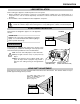
LENS REPLACEMENT AND INSTALLATION PROCEDURE NOTE: The installation procedure and needed parts for lens installation depend on the type of the Projection Lens. Check the Model No. of the Projection Lens and be sure to install or replace the lens following the procedure below. 1 Remove the Lower Lens Cover. Remove the two B (2) Screws A. Push the part B and pull the Lower Lens Cover down. (See Fig. 1.) A LOWER LENS COVER Fig-1 C 2 Remove the four (4) Screws C.
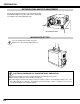
4 Replace the Lens Cap on the rear (mounting side) of the Projection Lens and mount a lens on the Lens Attachment with four (4) Screws. (Use the screws attached on the lens.) Connect the Lens Motor Lead connector to the socket on the right-top of the Lens Attachment (Motor Driven Lens only). See Fig. 5. When installing the LNS-W01, LNS-W01Z, LNS-T01, LNS-T01Z, be sure to mount the lens and the Light-Block Sheet Mounting Base on the Lens Mounting Bracket. (See Fig.
6 This projector has three Light-Block Sheets. Use the Light-Block Sheet corresponding with the lens. (Refer to the list below.) Set the Light-Block Sheet through the lens. Make sure the shape of the Light-Block Sheets are correct and be sure to set them as shown in the Fig. 8. NOTE: ● Be sure to set each Light-Block Sheet as shown in Fig. 8. ● Make sure the mark (TOP and BACK) on the Light-Block Sheets are correct and set them properly. Light-Block Sheets for each lens. Lens Model No. Type No.
7 Adjust the focus of the Projection Lens. (LNS-W01, LNS-W01Z, LNS-T01, LNS-T01Z, LNS-W03, 8 Replace the Upper Lens Cover. Fix the Upper Lens Cover with four (4) Screws C. (See Fig.2.) 9 Replace the Lower Lens Cover. Fix the Lower Lens Cover with two (2) Screws A. (See Fig.1.) 10 and LNS-W07 only.) Set up the projector and project an image on the screen. Loosen the Focus Lens Lock Screw and rotate the Projection Lens to obtain a proper focus.
FOCUS ADJUSTMENT (For Model LNS-W03 and LNS-W07) Set up the projector and project image on the screen. 1. Loosen the Focus Lock Screw on the projection lens. 2. Rotate the projection lens to obtain a proper focus on the center area of the screen. When the distance of the screen and lens is one (1) meter, set the ● mark (yellow) of the lens on the Focus Lock Screw position. ● mark (yellow) Focus Lock Ring 3. Lock the Focus Lock Screw securely.
Correcting the focus When the lens is attached to the projector and images are being projected on the screen, the peripheral focus may be out of focus in some localized areas. If this happens, insert the accessory in between the lens attachment and the lens to correct the focus. Inserting the spacers corrects the distance for the best diagonal focus at the screen. The corrected distance is determined by the thickness of the spacers that are used.
-8- 0.7 1.7 1.6 ----------1.3 1.2 ------ 8.5 6.0 NONE MIN MAX MIN MAX MIN MAX NONE MIN MAX LNS-W03 LNS-W05 LNS-W07 LNS-T03 LNS-W06 LNS-W04 6.3 NONE LNS-T01 LNS-T01Z 1.0 2.2 1.7 1.6 1.3 5.7 4.2 4.1 3.3 2.6 1.6 ----------- MIN MAX MIN MAX MIN MAX MIN MAX MIN MAX MIN MAX NONE 30" Zoom LNS-W01 LNS-W01Z LNS-S03 LNS-S01 LNS-M01 LNS-M01Z LNS-T02 LNS-W02 LNS-W02Z LNS-S02 LNS-S02Z Model No. 16.7 11.5 1.0 3.6 2.8 2.3 1.7 2.7 2.2 1.4 12.7 2.2 4.7 3.6 3.3 2.6 11.3 8.2 8.2 6.4 5.