SERVICE MANUAL Multimedia Projector Model No. LC-NB3E (U.S.A., Canada) ORIGINAL VERSION Chassis No. MM8-NB3E00 Give complete “Chassis No.” for parts order or serviceing, it is shown on the rating sheet on the cabinet on the projector. FOREWORD For your convenience, all service parts, identified in this manual are available through Eiki’s normal distribution channels.
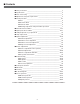
■ Contents ■ ■ ■ ■ ■ Safety instructions ________________________________________________3 Specifications __________________________________________________ 4 Note on Servicing ______________________________________________ 5 Adjustments after parts replacement ________________________________ 5 Circuit protections ______________________________________________ 6-7 ● Fuse ____________________________________________________ 6 ● Thermal switch ____________________________________________ 6 ● Interlock switc
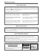
■ Safety Instructions SAFETY PRECAUTIONS WARNING: The chassis of this projector is isolated (COLD) from AC line by using the converter transformer. Primary side of the converter and lamp power supply unit circuit is connected to the AC line and it is hot, which hot circuit is identified with the line ( ) in the schematic diagram. For continued product safety and protection of personnel injury, servicing should be made with qualified personnel. The following precautions must be observed.
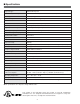
■ Specifications Projector Type Multi-media Projector Dimensions (W x H x D) 13.11” x 3.52” x 9.25” (333mm x 89.5mm x 235mm) Net Weight 8.6 lbs (3.9 kg) LCD Panel System 0.9” TFT Active Matrix type, 3 panels Panel Resolution 800 x 600 dots Number of Pixels 1,440,000 (800 x 600 x 3 panels) Color System 6 color system (PAL, SECAM, NTSC, NTSC4.43, PAL-M and PAL-N) High Definition TV SIgnals 480i, 480p, 575i, 575p, 720p. 1035i and 1080i Scanning Frequency H-sync. 15 ~ 100kHz, V-sync.
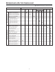
■ Adjustments after Parts Replacement ● : Adjustment necessary ❍ : Check necessary Optical Adjustments Disassembly / Replaced Parts LCD/ Prism Ass’y Condenser Lens Condenser lens adjustment ❍ ● Condenser lens-out adjustment ❍ Relay lens-out adjustment ❍ Condenser Lens-Out Polarized glass R G B P. F.
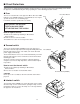
■ Circuit Protections This projector is equipped with the following circuit protections to operate in safety. If the abnormality occurs inside the projector, it will automatically turn off by operating one of the following protection circuits. ● Fuse The fuse is located inside of the projector. When either the LAMP Fuse indicator or the READY indicator is not illuminated, fuse may be opened. Check the fuse as following steps.
Circuit Protections ● Warning temperature and power failure protection The TEMP WARNING indicator flashes red and the projector will automatically turn off when the internal temperature of the projector exceeds the normal temperature or when stopping cooling fans or when the internal power supply lines are failed. Check the following possible causes and wait until stopping the TEMP WARNING indicator flashing. Possible causes - Air filter is clogged with dust particles.
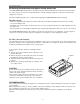
■ Mechanical Disassemblies Mechanical disassemble should be made following procedures in numerical order. Following steps show the basic procedures, therefore unnecessary step may be ignored. Caution: The parts and screws should be placed exactly the same position as the original otherwise it may cause loss of performance and product safety. 1 Cabinet Top and Control Panel removal 1 Remove 4 screws A to take the Cabinet Top Ass’y upward off.
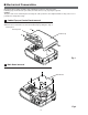
Mechanical Disassemblies 3 AV, AV Sub Board and Speaker removal 1 Remove 1 screw A to release a grounding wire. 2 Pull the Rear Panel ass’y upward. 3 Remove 4 screws B and take AV Board off. 4 Remove 4 screws C and take AV Sub Board off. 5 Remove 4 screws D and take Speaker off. AV board C AV Sub board B C C B B B D D A Speaker Fig.3 4 Front Panel and R/C Board removal 1 Remove 4 screws A and unhook 2 hooks B at the both of left and right side, and the take the Front Panel ass’y off.
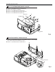
Mechanical Disassemblies 5 Lamp Ballast Unit removal 1 Remove 1 screw A and disconnect the Lamp Socket. 2 Remove 2 screws B to take the Lamp Ballast ass’y upward off. 3 Remove 4 screws C to take the Lamp Ballast Board off. B C B C C C A Lamp ballast board Fig.5 6 Filter Board removal 1 Remove 3 screws A and pull the Filter Board ass’y upward. 2 Remove 1 screw B to take the grounding lead from the cabinet bottom. 3 Remove 4 screws C to take the Filter Board off. A C C A Filter board C C A B Fig.
Mechanical Disassemblies 7 Power Box Cover and Fans(FN901, FN906) removal 1 Remove 4 screws A to take the Fan(FN901) off. 2 Remove 4 screws B to take the Fan(FN905) off. 3 Remove 3 screws C to take the Power Box Cover upward off. A A FN906 A A B B B C C B C Power box cover FN901 Fig.7 8-1 Optical Unit removal 1 Remove 1 screw A to take the Lamp Cover off. 2 Loosen 3 screws B to take the Lamp assembly by pulling the handle. Step to next procedure. Lamp ass’y B B B Lamp cover A -11- Fig.
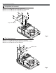
Mechanical Disassemblies 8-2 Optical Unit removal Step from previous procedure. 3 Remove 6 screws C to take the Optical Unit upward upward off. To mount optical unit, mount optical unit first then mount the Lamp assembly and Lamp Cover. C C C C C C Optical unit Fig.8-2 9 Power and P.F. Board removal B 1 Remove 8 screws A to take the Power Board ass’y upward off. 2 Remove 4 screws B to take the P. F. Board from the Power Board. 3 Remove 3 screws C to take the Power Board holder from the Cabinet Bottom.
Mechanical Disassemblies 10 Fan (FN905) removal 1 Remove 1 screw A and take a Washer, Spring and A Interlock Switch lever. 2 Pull the Fan and duct ass’y upward, then remove the 2 screws B to take the Fan (FN906) off. Interlock switch lever B B FN905 Fig.10 11 Temp Board and Fans (FN902, FN903, FN904) removal 1 Remove 1 screw A to take the Temp. Board off. 2 Remove 8 screws B and to take the Fan Duct B B B Top off and remove the Fans (FN902, FN903, FN904).
■ Optical Parts Disassemblies Before taking this procedure, remove Cabinet Top and Main Board following to the “Mechanical Disassemblies”. Disassembly requires a 2.0mm hex wrench and a screwdriver. Projection Lens removal 1 Remove the Front Panel following to “Front Panel Removal” on “Mechanical Disassemblies”. 2 Remove 4 screws to take the Projection Lens ass’y off. Fig.1 Integrator Lens-In disassembly 1 Remove 2 screws A and pull the Integrator Lens-In ass’y upward.
Optical Pats Disassemblies Condenser lens disassembly 1 Remove 2 screws A and pull the Condenser Lens ass’y upward. 2 Remove 4 screws B to take the Lens off from the holder. A A B Condenser Lens Holder B B B * Lens should be placed as the flat surface side comes to the holder side. Fig.3-2 Fig.3-1 Condenser Lens-Out disassembly 1 Remove 2 screws A and pull the Condenser Lens-Out ass’y upward. 2 Remove 2 screws B to take the Lens off from the holder.
Optical Parts Disassemblies Relay Lens-Out disassembly 1 Remove 2 screws A and pull the Relay Lens-Out ass’y upward. 2 Remove 2 screws B to take the Lens off from the holder. Note: There is no mounting direction of the lens. A B A Holder B Relay Lens-Out Fig.5-2 Fig.5-1 Polarized Glass-In removal 1 Remove each screw and pull the Polarized Glass-In ass’y upward. 2 Unhook the stoppers and take the glass off upward.
Optical Parts Disassemblies Polarized Glass-Out removal 1 Remove 4 screws A and take the LCD/Prism ass’y off upward from the optical unit. 2 Remove each screw B and take the glass off upward. A Note: Do not replace the LCD panel separately otherwise it can not obtain proper picture. A A LCD Panel/Prism Ass’y LCD Panel/Prism Ass’y B Polarized Glass-Out LCD Panel * Glass should be placed as the film attached side comes to the LCD panel side. Fig.7-2 Fig.
Optical Parts Disassemblies Locations and Directions Key No. When mounting or assembling the optical parts in the optical unit, the parts must be mounted in the specified location and direction as shown in figure below.
■ LCD Panel/Prism Ass’y Replacement IMPORTANT NOTICE on LCD Panel/Prism Ass'y Replacement LCD panels used for this model can not be replaced separately. Do not disassemble the LCD Panel/Prism Ass’y. These LCD panels are installed with precision at the factory. When replacing the LCD panel, should be replaced whole of the LCD panels and prism ass’y at once. After replacing LCD Panel/Prism ass’y, please check the following adjustments.
■ Lamp Replacement WARNING: - For continued safety, replace with a lamp assembly of the same type. - Allow the projector to cool for at least 45 minutes before you open the lamp cover. The inside of the projector can become very hot. - Do not drop the lamp module or touch the glass bulb! The glass can shatter and cause injury. Procedure 1 Turn off the projector and disconnect the AC cord. Allow the projector to cool for at least 45 minutes. 2 Remove a screw with a screwdriver and remove the lamp cover.
■ Optical Adjustments Before taking optical adjustments below, remove the Cabinet Top and Main Board following to the “Mechanical Disassemblies” Adjustments require a 2.0mm hex wrench and a slot screwdriver. When you adjust Condenser lens, Condenser lens-out or Relay lens adjustment, you need to disconnect some connectors and FPC cables of LCD panels on the main board.
Optical Adjustments Condenser Lens adjustment 1 Turn the projector on by a state of without FPC cables. 2 Project only green light on the screen. 3 Adjust the adjustment base of condenser lens assy to make color 4 uniformity in green. 1) If the shading appears on the left or right of the screen as shown in Fig.2-1, loosen 2 screws A with the 2.0mm hex driver, and adjust the slot B to make color uniformity in green by using a slot screwdriver.
Optical Adjustments Condenser Lens-Out adjustment 1 Turn the projector on by a state of without FPC cables. 2 Project green and blue lights on the screen. 3 Adjust the adjustment base of condenser lens-out assy to make color uniformity in cyan. 1) If the shading appears on the left or right of the screen as shown in Fig.3-1, loosen 1 screw A with the 2.0mm hex driver, and adjust the slot B to make color uniformity in cyan by using a slot screwdriver.
Optical Adjustments Relay lens-Out adjustment 1 Turn the projector on by a state of without FPC cables. 2 Project all of lights on the screen. 3 Adjust the adjustment base of relay lens assy to make color uniformity in white. 1) If the shading appears on the left or right of the screen as shown in Fig.4-1, loosen 1 screw A with the 2.0mm hex driver, and adjust the slot B to make color uniformity in white by using a slot screwdriver.
■ Electrical Adjustments ● Service Adjustment Menu Operation To enter the service mode To enter the “Service Mode”, press and hold the MENU and IMAGE button on the projector at the same time for more than 3 seconds. The service menu appears on the screen as follows. To adjust service data Select the adjustment group no. by pressing the MENU button, and select the adjustment item no. by pressing the pointer UP or DOWN button, and change the data value by pressing the VOLUME – or VOLUME + button.
Electrical Adjustments ● Circuit Adjustments CAUTION: The each circuit has been made by the fine adjustment at factory. Do not attempt to adjust the following adjustments except requiring the readjustments in servicing otherwise it may cause loss of performance and product safety. [Adjustment Condition] ● Input signal Video signal .......................... 1.0Vp-p/75Ω terminated, 16 steps gray scale (Composite video signal) Computer signal...................... 0.
Electrical Adjustments NRS adjustment Black Level adjustment 1. Receive the 16-step grey scale computer signal. 2. Set to COMPUTER mode. 3. Connect an oscilloscope to test point “TP3551” (+) and chassis ground (-). 4. Enter the service mode, select group no. “3”, item no. “7” and change data value to adjust amplitude “a” to be 4.8 ±0.1V. 1. Receive the 16-step grey scale computer signal. 2. Set to COMPUTER mode. 3. Enter the service mode. [R-BLACK ADJUSTMENT] 4.
Electrical Adjustments PC Offset adjustment PC Gain adjustment 1. Receive the 16-step gray scale computer signal. 2. Set to COMPUTER mode. 3. Enter the service mode. 1. Receive the 16-step gray scale computer signal. 2. Set to COMPUTER mode. 3. Enter the service mode. [R-OFFSET ADJUSTMENT] 4. Connect an oscilloscope to test point “TP25R1” (+) and chassis ground (-). 5. Select group no. “3”, item no. “11” and change data value to adjust the waveform “a” (black portion ) to be maximum amplitude.
Electrical Adjustments AV Gain adjustment Gamma Shift adjustment 1. Receive the 16-step gray scale video signal. 2. Set to VIDEO mode. 3. Enter the service mode. [PC-GAMMA OFF ADJUSTMENT] 1. Receive the 16-step gray scale computer signal. 2. Set to COMPUTER mode. 3. Enter the service mode, select group no. “2”, item no. “6” and change data value to reproduce the proper gray scale picture on the screen. [R-GAIN ADJUSTMENT] 4. Connect an oscilloscope to test point “TP25R1” (+) and chassis ground (-). 5.
Electrical Adjustments ● Service Adjustment Data Table No. Adjustment Item Initial Value Group: 0 TB1274 0 TINT 1 SHP_EQ 2 SHP_FO 3 4 5 SHP_GAIN Y_OUT_LEVEL C_OUT_LEVEL SECAM,NT4.43 S-Video 8 8 9 9 NTSC NT4.43 PAL SECAM 7 8 9 10 11 12 13 COL_SYS X’TAL NOISE_DET V_FREQ Vert.
Electrical Adjustments No.
Electrical Adjustments No.
Electrical Adjustments No.
Electrical Adjustments Test Points and Locations ● MAIN BOARD TP52R TP11SC TP52G TP52B TP11SY TP62V TP62H TP11CV TP25G1 TP201G TP11PB TP201B TP11PR TP25G2 TP201R TP3551 IC4101 TP205 K25R K25B K25G IC301 TP25B2 TP25R1 TP25B1 TP25R2 TPDVS TPDCLK TP12V2 TP3581 IC401 IC801 K8P TP12V1 TPDHS -34-
■ Troubleshooting No Power - Abnormality on lamp ballast drive signal (BALLAST_AC). BALLAST_AC signal is output from pin 39 of IC801 and sent to pin 11 of IC1881, and output from pin 9 by the name of BALLAST_AC1 signal. BALLAST_SW1 signal drives the lamp ballast unit. Check BALLAST_AC and BALLAST_AC1 signals and lamp ballast unit. - Abnormality on fan drive signal (FAN DRIVE).
Troubleshooting Power supply drive and protection diagrams and locations SW902 IC2881 F601 SW904 SW902 Thermal sw. Interlock sw. F601 Fuse AC IN IC4881 SW904 LAMP Ass'y LAMP BALLAST UNIT P.F BOARD 1 1 3 3 IC4881 TEMP. SENS. K48E CB2 IC611 P.F.CONTROL 1 3 TEMP. SENSOR BOARD K6E 1 4 7 1 4 7 FN905 FN906 3 1 1 K8B K6F K6J 2 LAMP_ERR IC671 6V K6K K6M K6L K8E K8S 15.5V Power Oscillator Circuit -6V P-FAIL Failure: High IC2881 TEMP.
Troubleshooting No Picture 3. No picture from both of Video and Computer sources. The possible causes of No Picture are listed below. Please check following and refer to video signal processing diagrams in the figure opposite. Check RGB signals at test points TP52R, TP52G and TP52B. Check RGB signals at test points TP201R, TP5201G and TP201B. Check HSYNC signal at test point TP205. Check Sync signals at test points at TP62H and TP62V. 1.
15 16 19 20 H-SYNC V-SYNC VIDEO/Y Pb/Cb Pr/Cr S-VIDEO 15 12 10 IC5161 33 34 35 36 45 46 49 50 51 52 39 41 5 2 3 TP11SC Cr Cb CV CV/Y TP11CV TP11PB TP11PR Y/C 13 14 B G B 9 4 R G R R G B 2 19 Y 7 7 C C_SWIN IC2101 DIGITAL COMB FILTER 9 5 23 22 Cr Cb Y 16 18 20 8 12 V H 1 5 13 11 12 10 4 8 Y Pb Pr HS_OUT VS_OUT IC6101 INVERTER 5 1 2 V H IC6171 AFC 13 DET TP52B TP52G TP52R 16 17 1 IC6251 INVERTER PC: H AV: L AV_HSYNC AV_VSYNC V H A
Troubleshooting No Sound 1. No audio signals at AV input circuit. Check MUTE signal at pin 7 of IC1831, pins 7 and 13 of IC1881, and peripheral circuit. Mute On : High Check sound volume signal at pins 27, 28 of K10U, and pin 14 of IC1831.Check IC IC001, IC031 and peripheral circuit. Volume Min.: Low Check audio signals at pins14 and 15 of IC5011 on AV Board. Check IC5011 and peripheral circuits. 2. Incorrect operation of VIDEO/COMPUTER mode switching.
■ Control Port Functions ● System Control & I/O Port Table (IC801) Pin No.
Control Port Functions Pin No.
Control Port Functions ● IIC Bus I/O Expander (IC1851) Port Functions Pin No. 1 2 3 4 5 6 7 8 9 10 11 12 13 14 15 16 Name S SCL SDA D0 D1 D2 D3 VSS D4 D5 D6 D7 VDD CS2 CS1 CS0 Function Action Reset IIC SCL IIC SDA CARD_IN VIEWER_ON SCDT1 TURBO_LED GND WARNING_LED LAMPREP_LED READY_LED Not used 5V Chip Select 2 Chip Select 1 Chip Select 0 Open Active “L” Active “L” L: CARD H: No CARD L: VIEWER Unit exist DVI Sync.
Control Port Functions ● IIC Bus DA Converter (IC2161) Port Functions Pin No.
■ Waveforms VIDEO-IN Y-IN C-IN Y-OUT CB-OUT CR-OUT H-SYNC OUT V-SYNC OUT R-OUT G-OUT B-OUT R-DRIVE G-DRIVE B-DRIVE -44-
Waveforms H-SYNC OUT V-SYNC OUT H-SYNC IN H-SYNC DRIVE V-SYNC DRIVE DHS DVS NRS R-S&H OUT G-S&H OUT BALLAST SW -45- B-S&H OUT
■ Cleaning After long periods of use, dust and other particles will accumulate on the LCD panel, prism, mirror, polarized glass, lens, etc., causing the picture to darken or color to blur. If this occurs, clean the inside of optical unit. Remove dust and other particles using air spray. If dirt cannot be removed by air spray, disassemble and clean the optical unit. Cleaning with air spray Disassembly Cleaning 1. Remove the cabinet top following to “Mechanical Disassemblies”. 2.
■ IC Block Diagrams ● AD8183ARU ● BA6287F -47-
IC Block Diagrams ● BA7078AF ● CXA2101AQ -48-
IC Block Diagrams ● CXD2064Q ● L3E01031 -49-
IC Block Diagrams ● L3E06070 ● L3E07050 -50-
IC Block Diagrams ● ML60851 ● M62393 -51-
IC Block Diagrams ● TB1274AF
IC Block Diagrams ● FA7612CA ● STR-Z2156 -53-
-54-
■ Electrical Parts List MM8-NB3E00 Product safety should be considered when a component replacement is made in any area of a projector. Components indicated by a ! mark in this parts list and the circuit diagram show components whose value have special significance to product safety. It is particularly recommended that only parts specified on the following parts list be used for components replacement pointed out by the mark.
MM8-NB3E00 Electrical Parts List Note: Parts order must contain Chassis No., Part No., and Descriptions. ● OUT OF CIRCUIT BOARD Interlock switch (SW904) Thermal Switch (SW902) Lamp Ballast Unit F601 Fuse FN906 Cooling Fan Line Filter Board AV Sub Board FN901 Cooling Fan P.F.
MM8-NB3E00 Electrical Parts List Key No. Part No. Description Key No. ASSEMBLIED BOARDS ! ! ! ! ! ! ! ! ! 610 610 610 610 610 610 610 610 610 292 299 299 294 294 297 297 297 297 5609 4162 7293 1708 1715 1798 1804 1828 1873 ASSY,PWB,KEY SW MS6A ASSY,PWB,P.F.
MM8-NB3E00 Electrical Parts List Key No. R618 R619 R62A R62B R62C R62D R62E R62F R62G R62H R62I R62J R62L R62P R62Q R62R R620 R623 Part No.
MM8-NB3E00 Electrical Parts List Key No. R5505 R5506 R5551 R5552 R5553 R5554 R5555 R5556 R63B R63C R63D R63E ! R633 R634 R635 R636 R637 R638 R643 R645 R65A R65B R65C R65E R65G R65H R65I R65J R65K R65U R65V R65W R65X R65Y R65Z R651 R652 R653 R654 R655 R656 R657 R658 R659 R66A R66B R660 R661 R662 R663 R664 R67A R67B R67C R67D R67E R67F R67G R67H R67I R67K R671 R672 R673 R674 R675 R676 Part No.
MM8-NB3E00 Electrical Parts List Key No. D69B D69C Part No. 407 004 0706 407 004 0706 MISCELLANEOUS PC641 408 039 3502 ! PC642 408 039 3502 ! PC643 408 039 3502 ! Description Key No.
MM8-NB3E00 Electrical Parts List Key No. IC3011 IC3041 IC5011 IC5161 Part No. Description Key No.
MM8-NB3E00 Electrical Parts List Key No. Part No. Description Key No.
MM8-NB3E00 Electrical Parts List Key No. D2057 D2058 D2059 D2811 D2812 D3001 D3002 D3003 D3004 D3006 Part No. 407 407 407 407 407 407 407 407 407 407 Description 187 187 187 179 179 179 179 179 187 187 8209 8209 8209 0501 0501 0501 0501 0501 8209 8209 ZENER ZENER ZENER ZENER ZENER ZENER ZENER ZENER ZENER ZENER DIODE DIODE DIODE DIODE DIODE DIODE DIODE DIODE DIODE DIODE UDZ12B-TE-17 UDZ12B-TE-17 UDZ12B-TE-17 UDZ6.2B-TE-17 UDZ6.2B-TE-17 UDZ6.2B-TE-17 UDZ6.2B-TE-17 UDZ6.
MM8-NB3E00 Electrical Parts List Key No. Part No. MISCELLANEOUS X6171 645 046 9213 Description Key No. OSC,CERAMIC 503.
MM8-NB3E00 Electrical Parts List Key No. Q3111 Q3112 Q3113 Q3162 Q3163 Q3171 Q3172 Q3181 Q3182 Q3591 Q3592 Q4171 Q4172 Q6126 Q6127 Q6137 Q8121 Q8122 Q8141 Part No.
MM8-NB3E00 Electrical Parts List Key No. IC5241 IC5251 IC5261 IC5271 IC5281 IC5291 IC531 IC561 IC6101 IC6121 IC6141 IC6211 IC6221 IC6241 IC6251 IC6261 IC6271 IC6281 IC6621 IC6631 IC6641 IC6651 IC6661 IC6671 IC801 IC8121 IC8131 IC841 IC9801 Part No. Description Key No.
MM8-NB3E00 Electrical Parts List Key No. C2103 C2104 C2105 C2106 C211 C2111 C2112 C2113 C2117 C2118 C2119 C212 C2121 C2124 C2126 C2127 C213 C2161 C2162 C2163 C2164 C221 C2501 C2502 C2503 C2506 C2507 C2508 C251 C2511 C2512 C2513 C2516 C2517 C2518 C2521 C2522 C2523 C2526 C2527 C2528 C2571 C2572 C2573 C2591 C2807 C2821 C2822 C2823 C2882 C301 C302 C303 C304 C306 C307 C308 C309 C3101 C3102 Part No.
MM8-NB3E00 Electrical Parts List Key No. C406 C407 C408 C409 C4102 C4103 C4104 C4105 C4106 C411 C4116 C412 C4127 C413 C4134 C4137 C4138 C4139 C414 C4141 C4142 C4143 C4144 C4146 C4147 C4148 C4149 C4151 C4152 C4153 C4154 C4156 C4158 C4159 C416 C4161 C4162 C4163 C4164 C4166 C4167 C4168 C4169 C417 C4176 C4177 C418 C4186 C419 C421 C422 C423 C501 C502 C503 C504 C506 C507 C508 C509 C511 C512 C513 Part No.
MM8-NB3E00 Electrical Parts List Key No. C568 C569 C571 C572 C573 C581 C582 C6101 C6121 C6127 C6131 C6141 C6147 C6151 C6202 C6204 C6211 C6212 C6216 C6221 C6222 C6226 C6241 C6242 C6243 C6244 C6245 C6246 C6247 C6248 C6249 C6251 C6261 C6265 C6266 C6267 C6268 C6271 C6281 C6601 C6602 C6603 C6604 C6606 C6607 C6611 C6612 C6613 C6614 C6616 C6617 C6621 C6622 C6623 C6624 C6631 C6632 C6633 Part No.
MM8-NB3E00 Electrical Parts List Key No. RB1446 RB301 RB302 RB303 RB304 RB305 RB306 RB307 RB308 RB309 RB310 RB311 RB312 RB3821 RB411 RB412 RB413 RB414 RB415 RB416 RB501 RB502 RB503 RB531 RB532 RB533 RB561 RB562 RB563 RB9801 RB9802 R110 R1101 R1102 R1103 Part No.
MM8-NB3E00 Electrical Parts List Key No. R152 R153 R154 R156 R157 R158 R1581 R1582 R1583 R1584 R1586 R1587 R1588 R1589 R159 R1591 R1592 R1593 R171 R172 R173 R174 R176 R177 R178 R1801 R1802 R1816 R1817 R1818 R1819 R1831 R1832 R1833 R1834 R1836 R1837 R1851 R1852 R1853 R1855 R1861 R1862 R1863 R1864 R1876 R1877 R1878 R1879 R1881 R1882 R1883 R1884 R1886 R1887 R1888 R1889 R1891 R1892 R204 R205 R207 R2101 R2102 R2103 R2104 R2105 Part No.
MM8-NB3E00 Electrical Parts List Key No. R2549 R2550 R2551 R2552 R2553 R2554 R2555 R2556 R2557 R2558 R2559 R2560 R2561 R2562 R2571 R2572 R2576 R2577 R2581 R2584 R2591 R2806 R2807 R2821 R2822 R2823 R2824 R2825 R2826 R2841 R2842 R2843 R2844 R2851 R2852 R2853 R2854 R2856 R2857 R2858 R2861 R2862 R2866 R2867 R2868 R2877 R2881 R2882 R2883 R2884 R2887 R2889 R2891 R301 R302 R306 R308 R3100 R3101 R3102 R3103 R3104 R3105 R3106 R3107 R3108 R3109 Part No.
MM8-NB3E00 Electrical Parts List Key No. R3544 R3545 R3546 R3547 R3552 R3553 R3556 R3558 R356 R3561 R3562 R3563 R3564 R3565 R3567 R3568 R3569 R3570 R3571 R3573 R3574 R3575 R3576 R3577 R358 R3581 R3582 R359 R3591 R3592 R3593 R3594 R361 R362 R364 R366 R368 R371 R3801 R3802 R3803 R3804 R3806 R381 R3821 R3822 R3823 R383 R3831 R3832 R3835 R384 R3841 R3842 R3843 R3844 R3846 R3847 R3848 R387 R388 R391 R392 R393 R394 R4103 R4104 Part No.
MM8-NB3E00 Electrical Parts List Key No. R457 R458 R459 R461 R462 R463 R464 R466 R467 R468 R469 R471 R472 R473 R504 R507 R5201 R5202 R5203 R521 R5211 R5212 R5213 R5214 R5215 R5216 R5217 R5218 R5219 R5221 R5222 R5223 R5224 R5225 R5226 R523 R5231 R5232 R5233 R5234 R5235 R5236 R524 R5241 R5243 R5245 R5248 R5251 R5252 R5253 R5254 R5255 R5256 R5257 R5258 R5259 R5261 R5262 R5271 R5274 R5276 R5277 R5278 R5281 R5284 R5286 R5287 Part No.
MM8-NB3E00 Electrical Parts List Key No. ! R6616 R6619 R6622 R6623 R6624 R6652 R6661 R6671 R6672 R801 R802 R803 R804 R806 R807 R808 R811 R812 R8121 R8122 R8126 R8127 R8128 R8129 R8131 R8132 R814 R8141 R8143 R816 R818 R819 R821 R822 R823 R826 R827 R828 R831 R832 R834 R836 R841 R842 R846 R847 R848 R851 R856 R857 R858 R861 R862 R866 R867 R868 R871 R872 R873 R874 R876 R877 R878 R879 R881 R882 R883 Part No.
MM8-NB3E00 Electrical Parts List Key No. D2842 D2843 D2844 D3111 D3112 D3161 D3171 D3591 D3801 D3802 D3821 D3831 D6126 D6127 D6131 D6132 D6146 D6151 D6211 D6212 D6213 D6214 D6223 D6224 D6602 D6606 D6611 D6621 D6631 D6641 D6642 D6661 D6662 D801 D802 D8122 D8126 D856 D857 Part No.
MM8-NB3E00 Electrical Parts List Key No. Part No. Description Key No. -77- Part No.
■ Mechanical Parts List MM8-NB3E00 Note: Parts order must contain Chassis No., Part No., and Descriptions.
MM8-NB3E00 Mechanical Parts List Key No. Part No. Description Key No.
■ Optical Parts List MM8-NB3E00 44 44 46 56 46 46 44 44 46 46 -80- 57
MM8-NB3E00 Optical Parts List 44 44 54 44 44 67 (Red) 68 (Green) 69 (Blue) 44 -81-
MM8-NB3E00 Optical Parts List 43 43 43 53 53-a (Red) 53-b (Green) 53-c (Blue) 44 44 46 46 61 -82-
MM8-NB3E00 Optical Parts List 45 45 45 45 52 52 52-a -83-
MM8-NB3E00 Optical Parts List 63 55 51 66 64 62 70 57 58 71 60 59 65 -84-
MM8-NB3E00 -85-
MM8-NB3E00 -86-
MM8-NB3E00 -87-
A-key to better communications U.S.A. Canada EIKI International, Inc. 30251 Esperanza Rancho Santa Margarita CA 92688-2132 U.S.A. Tel : 800-242-3454 (949)-457-0200 Fax : 800-457-3454 (949)-457-7878 E-Mail : usa@eiki.com EIKI CANADA - Eiki International, Inc. P.O. Box 156, 310 First St. - Unit 2, Midland, ON, L4R 4K8, Canada Tel : 800-563-3454 (705)-527-4084 Fax : 800-567-4069 (705)-527-4087 E-Mail : canada@eiki.