
Technical data

48
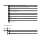
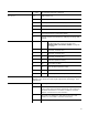
AT +MF=<data bits><parity>,<top
bits>
Data bits: 8,7,5. Parity: N (none), O (odd), E (even), S (space), M (mark).
Stop bits: 1, 2. The transmission rate is derived from the currently
selected Rx/Tx transmission speed (+MS command). Example:
AT+MF=8,N,1 - select 8 data bits, no parity and one stop bit.
AT +MF? Returns currently selected framing.
AT +MF=? Returns list of supported parameters.
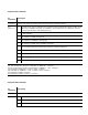
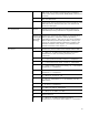
AT +MS? Modulation Selection Query. The response to the query has the following
format: AT +MS: <mod>,<auto>,<min>,<max>,<min_rx>,<max_rx>.
AT
+MS=[<mod>][,[<auto>][,[<min
>][,[<max>][,[<min_rx>][,[<max
_rx>]]]]]]
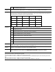
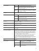
Modulation Selection Set. Modulation: B103 (300 bps), B212A (1200 bps),
V21 (300 bps), V22 (1200 bps), V22B (1200 - 2400 bps), V22F (1200 bps
Dialogic
®
Diva
®
Fast Setup), V22BF (1200 - 2400 bps Diva Fast Setup),
V23C (Tx:75 bps/Rx:1200 bps outgoing call, Tx:1200 bps/Rx:75 bps
incoming call), V23HDX, V23HDXON (1200 bps half duplex for SMS over
PSTN, off/on hook standard), V32 (4800 - 9600 bps), V32B, (4800 -
14400 bps), V34 (2400 - 33600 bps), V90 (28000 - 56000 bps download
client <- server, 28000 - 32000 bps upload client -> server), V90a (28000
- 56000 bps upload client -> server, 28000 - 32000 bps download client
<- server). Auto: 0 - use only the specified modulation, 1 - try other
modulations with lower data rates if the specified modulation cannot be
used. min: Minimum transmit data rate. max: Maximum transmit data
rate. min_rx: Minimum receive data rate. max_rx: Maximum receive data
rate. Only V90 modulation has different transmit/receive rates. Rate = 0
means no minimum or maximum limitation. Valid Rate Values (in bps):
75, 300, 600, 1200, 2400, 4800, 7200, 9600, 12000, 14400, 16800,
19200, 21600, 24000, 26400, 28000, 28800, 29333, 30667, 31200,
32000, 33600, 33400, 34667, 36000, 37333, 38000, 38667, 40000,
41333, 42000, 42667, 44000, 45333, 46000, 46667, 48000, 49333,
50000, 50667, 52000, 53333, 54000, 54667, 56000, 0
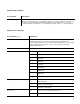
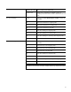
Notes:
[a] "AT+" commands are Dialogic
®
Diva
®
-specific commands which may be used either as part of a normal AT
command or as part of a called party number.
[b] If you use this AT command in sequence (in one line) with other AT commands, it should either be the last
command or it should be followed by a semi-colon ";". For example: the AT-command sequence AT&F14,
AT#CID=7, ATS0=1, AT+IA12 can be written as: AT&F14#CID=7S0=1+IA12 or AT&F14+IA12;#CID=7S0=1
[c] If a subaddress (SUB) needs to be entered, it must be separated from the rest of the number by a vertical
character [|] (also called the pipe symbol).
[d] If supported by used bearer protocol (for example V.110).
[e] Determines if the ASYNC/SYNC conversion module is inserted on top of OSI Layer 3 and which mode this
module assumes. See ASYNC/SYNC conversion module on page 54 for details.
[f] Commonly used values are: 1/1 - ISDN voice call 3.1 kHz, 1/2 - Analog voice call, 1/3 - ISDN voice call 7
kHz, 2/1 - Fax group 2, 2/2 - Fax group 3, 2/3 - Data over modem connection, 2/4 - BTX over modem
connection, 7/0 - 64 kbps Data, 7/170 - 56 kbps Data, 7/197 - V.110 rate adaptation. See Call parameter
(BC/LLC) selection on page 57 for details.