Eiconcard S5x Family for ISA-Compatible Bus www.eicon.
Fourth Edition (July 2001) 203-078-04 Eicon, Eiconcard, and the Eicon logo are either trademarks or registered trademarks of Eicon Networks Corporation. Changes are periodically made to the information herein; these changes will be incorporated into new editions of the publication. Eicon Networks may make improvements and/or changes in the products and/or programs described in this publication at any time. Copyright © 1996-2001 Eicon Networks Corporation.
Table of Contents Introduction ................................................................... 5 Installing the Eiconcard S5x.......................................... 6 Making an ISDN Connection......................................... 9 Connecting to an Eicon Networks NT1....................................... 9 Connecting to a Third Party NT1 ................................................ 9 Termination ...............................................................................
www.eicon.
Introduction The S5x family of Eiconcards are ISA cards that offer X.25 connectivity through one or two (depending on the the Eiconcard model) high-speed ports (supporting V.24, V.35, or X.21 interfaces) at speeds of up to 512 Kbps, and/or through an ISDN BRI port (Eiconcard S51) at speeds of up to 128 kbps (over the “D” channel or the “B” channels). Note The Eiconcard S5x also supports protocols such as SDLC, PPP, and Frame Relay.
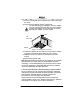
Installing the Eiconcard S5x Follow the steps below to install the Eiconcard S5x. If you want the Eiconcard S5x to be available to multiple users on a LAN, install it in the PC that will function as a gateway for the LAN. 1 Prepare the PC Turn off the PC and disconnect its power cable. Remove the cover of the PC according to the instructions that came with it. 2 Prepare the Eiconcard Prepare the Eiconcard S5x by selecting its I/O address and communications interface. a) Set the I/O address.
If there is a metal plate at the end of the slot, remove it and keep the screw. d) Firmly insert the adapter into the selected slot. To avoid damaging your hardware, insert the adapter only into a slot with the same bus type as the adapter. Inserting the adapter into any other type of slot can damage your adapter, your PC, or both. c) screw ISA Eiconcard ISA slot Figure 2. Inserting the Eiconcard S5x.
5 Test the Eiconcard S5x The application software purchased with the Eiconcard S5x contains a test program to verify the card’s integrity. Consult the documentation supplied with this software for details. 6 Connect to the outside world You are now ready to connect the Eiconcard S5x to the outside world. • To set up ISDN connections, consult “Making an ISDN Connection” on page 9. • To set up an HSI connection, consult “Making an HSI Connection” on page 13.
Making an ISDN Connection Note Only the Eiconcard S51 supports ISDN connections. After you have installed your Eiconcard S51, connect your ISDN line. • If you plan to use an Eicon Networks NT1, see “Connecting to an Eicon Networks NT1,” below. • If you plan to use a third party NT1 or if you are installing the Eiconcard S51 outside of North America, see “Making an HSI Connection” on page 13.
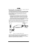
Connecting to a Third Party NT1 To connect to a third party NT1, you must use the ISDN S/T Cable. This cable includes interface circuitry which is not normally provided by the third party NT1 (but which is provided by Eicon’s NT1). Plug the ISDN S/T Cable into the DIN-4 port on the card as illustrated in Figure 4. • In North America and Australia, you may need to insert the RJ-45 plug into the terminating resistor, and then insert the terminating resistor into the S/T connector.
Termination This section applies to S/T interface users in Australia and North America, and provides instructions to help set up termination scenarios. Termination requirements vary according to: the number of devices connected to the NT1; and the distance between the devices and the NT1. For users who require termination, the Eiconcard S51 S/T has been shipped with a separate terminating resistor.
Multiple ISDN Devices If the NT1 is connected to more than one ISDN device, follow the procedures below. 75 meters or more If the connection spans 75 meters (250 feet) or more, both end devices on the ISDN bus must be set to 100 ohm termination. If the Eiconcard is one of the end devices, connect the 100 ohm terminating resistor included with the ISDN cable. Consult the manuals provided with the other ISDN devices and NT1 for more details.
Making an HSI Connection The Eiconcard S5x can connect as a DTE to devices such as Data Service Units (DSUs) which support one of the following interfaces: V.24, V.35, or X.21. It can also connect directly to a host computer, or back-to-back to another Eiconcard. Each HSI port is configured independently Table 1 lists the most common connections supported by the HSI port, and specifies the part number of the required Eicon Networks cable.
Interface Specifications The standards compliant with the interfaces supported on the HSI port are listed in Table 2. The rest of this section describes the allocation of pins used to implement the electrical and signalling requirements of each interface. Interface Standard Compatibility V.24 CCITT V.24 Signalling CCITT V.28 Electrical V.35 X.21 CCITT X.21bis Electrical and signalling RS-232-C Electrical and signalling ISO 2110 Connector type for the DCE side of a V.
Cable Construction Information If you plan to construct your own HSI cables, be sure to observe the guidelines given below. Wire Gauge, Grounding, and Pairing • Use 26 or 24 AWG wire. Contacts should be 30 microinch gold flash. • The cable must be grounded both by a drain wire connected to pin 1 on both sides (pin A on the type M connector) and by the braid. Both the drain wire and the braid must be connected to the connector case and shell at each end of the cable.
The V.24 Interface 1 10 19 A pin-out diagram for the V.24 DCE interface is shown in Figure 5. The signal definitions and names are listed in Table 4. PGND TXD RXD RTS CTS DSR SGND DCD TEST DTR RLB RI TCLK DTECLK TI RCLK Figure 5. V.
The V.35 Interface A pin-out diagram for the V.35 interface is shown in Figure 6. The signal definitions and names are listed in Table 5. 1 10 19 RCLKPGND RXD+ RTS CTS DSR CLK+ SGND DCD RCLK+ TXD+ DTR RXDRLB CLKRI TCLK+ TCLKTI TXDTEST Figure 6. V.
The X.21 Interface 1 10 19 A pin-out diagram for the X.21 interface is shown in Figure 7. The signal definitions and names are listed in Table 6. S(B) PGND R(A) R(B) I(B) B(A) I(A) SGND T(A) C(B) B(B) C(A) T(B) S(A) Figure 7. X.
Null-Modem Cables The wiring diagrams below shows the connections required to construct a back-to-back HSI—HSI cable, and V.35 - AS/400 cable. For additional information required to construct your own cables, see “Cable Construction Information” on page 15. TWISTED PAIRS (MANDATORY) HSI 1 2 3 4 5 6 7 8 DRAIN WIRE HSI 1 3 2 8 20 7 4 5 9 14 10 16 13 23 11 12 19 26 10 23 9 14 24 13 16 15 17 19 26 20 24 11 12 6 15 17 BRAID Figure 8. HSI V.24/V.
TWISTED PAIRS (MANDATORY) HSI HSI DRAIN WIRE 1 7 11 12 13 16 19 26 20 24 1 7 19 26 20 24 11 12 13 16 BRAID Figure 9. HSI X.21 Null-Modem Cable (300-032) TWISTED PAIRS (MANDATORY) HSI 1 4 5 6 7 8 14 9 10 23 11 12 Type M DRAIN WIRE A F H B C D U W P S X AA V Y R T E 13 16 19 26 20 BRAID Figure 10. HSI V.
TWISTED PAIRS (MANDATORY) HSI 1 2 3 4 5 6 7 8 DRAIN WIRE HSI 1 3 2 8 20 7 4 5 9 14 10 16 13 23 11 12 19 26 10 23 9 14 24 13 16 15 17 19 26 20 24 11 12 6 15 17 BRAID Figure 11.
Appendix Setting the I/O Address The Eiconcard S5x is shipped with the I/O address set to 380h. This setting only needs to be changed if another card in your PC uses an I/O address in the range 380h to 387h. You can set the Eiconcard to use any of the standard I/O addresses listed in Table 7. Remember that no other card can use the same address, or the next seven higher values (for example, if you choose 378, no other card can use any value from 378 to 385).
Setting I/O Addresses when Installing Multiple Eiconcards If you are installing two or more Eiconcards in the PC, for every Eiconcard installed at a primary I/O address, you can install one at a secondary I/O address. This reduces the number of I/O addresses consumed since primary and secondary I/O addresses occupy the same position in the PC I/O address space. Primary and secondary I/O addresses differ in the setting of switch 1, as described in Table 8.
Selecting an Interface The Eiconcard S5x is capable of connecting as a DTE to devices which support the V.24, V.35, or X.21 interface. It can also connect directly to a host computer or back-to-back to another Eiconcard. The Eiconcard S5x is shipped with the HSI port set to the V.24 and V.35 interfaces. If you wish to use the X.21 interface, you must reposition the jumper located next to the HSI connector. To change the jumper from position A (V.24/V.35) to position B (X.
Software Configuration Use the information below to assign the card’s interrupt request level and memory segment address. Interrupt Request Level Only one device can use each interrupt request level (IRQ). Make sure you assign an unused IRQ to the Eiconcard S5x. The usual assignment of IRQs in a PC is listed in Table 9. You may be able to make additional IRQs available by disabling serial port 2 and parallel port 2. Consult your PC manual for details.
LED Functionality Eiconcard S50, S52 Note The Eiconcard S50 has only one HSI port. Configuration Status This status light illuminates during configuration to indicate which card and/or port is being configured. This is most useful when more than one Eiconcard is installed in the PC. Consult the documentation provided with the configuration software for information about this status light.
Eiconcard S51 The Eiconcard S51 has three status lights (LEDs) on the end bracket. Two of these lights indicate the status of the ISDN connection, and the third identifies the card during configuration. D-channel Status The D-channel controls the link to your ISDN service provider. Off ..........The line is not active. The cable may not be connected. Blinking .. The line is active, but a link can’t be established. This may be a symptom of incorrect configuration. Steady....
Technical Specifications Technical Data • IBM PC, PC AT, and PS/2 Model 30 bus compatible Eiconcard CPU/Memory # of HSI Ports #of ISDN BRI Ports Eiconcard S50 20 MHz Motorola 68302 / 2 MB RAM 1 N/A Eiconcard S51 20 MHz Motorola 68302 / 2 MB RAM 1 1 Eiconcard S52 20 MHz Motorola 68302 / 2 MB RAM 2 N/A Hardware Installation • Interrupt levels selectable via software (2, 3, 4, 5, 6, 7, 10, 11, 12, 14, 15) • I/O address selectable via on-board switch (14 options) • 4Kb shared memory access with
International Regulatory Information Regulatory Information for the USA: WARNING. Changes or modifications to this unit not expressly approved by Eicon Networks Corporation could void the user's authority to operate the equipment.
FCC Part 68 Notice This unit complies with Part 68 of the FCC rules. On the bottom of this equipment is a label that contains, among other information, the FCC registration number. If requested, this information must be provided to the telephone company. An FCC compliant telephone cord and modular plug is provided with this equipment, designed to be connected to the telephone network or premises wiring using a compatible modular jack which is Part 68 compliant.
Regulatory Information for Canada NOTICE: The Industry Canada label identifies certified equipment. This certification means that the equipment meets certain telecommunications network protective, operational and safety requirements. Industry Canada does not guarantee the equipment will operate to the user’s satisfaction. Before installing this equipment, users should ensure that it is permissible to be connected to the facilities of the local telecommunications company.
Regulatory Information for Europe EU Declaration of Conformity EN: Eicon Networks Corporation declares that this equipment is in compliance with the essential requirements and other relevant provisions of Directive1999/5/EC. DE: Eicon Networks Corporation erklärt, daß diese Telekommunikations-endeinrichtung den grundlegenden Anforderungen und anderen relevanten Bestimmungen der Richtlinie 1999/5/EG entspricht.
Safety Status: SELV No voltages within this equipment exceed SELV voltages. All interconnection points and ports are SELV. User/Installer Instructions for the United Kingdom Important Safety Considerations When Installing Into A Host Computer System The Eiconcard S5x is a single PCI card.
Regulatory information for Australia • This customer equipment shall only be installed in a PC that requires the use of a tool to gain access to internal parts (e.g. this customer equipment must not be installed in a PC with a ‘flip lid’). • Proper installation of the Eiconcard S5x card requires that it is screwed to the metal backplate of the computer. This ensures proper grounding, which is necessary for safety purposes.
203-078-04