
User manual


Selecting an Interface Cable 141
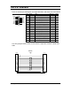
The X.21 Interface
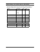
The X.21 interface pin-out diagram and signal definitions and names are shown below.
The wiring diagram below shows the connections required to construct a VHSI-V.35
cable.
Pin # Signal Name Direction CCITT #
1/15 PGND Protective Ground Common 101
2 T(A) Transmit Data (+) Output 103A
3 C(A) Control Signal (+) Output 105A
4 R(A) Receive Data (+) Input 104A
5 I(A) Indication (+) Input 109A
6 S(A) Signal Element Timing (+) Input 115A
7 B(A) Byte Timing (+) Input 114A
8 SGND Signal Ground Common 102
9 T(B) Transmit Data (-) Output 103B
10 C(B) Control Signal (-) Output 105B
11 R(B) Receive Data (-) Input 104B
12 I(B) Indication (-) Input 109B
13 S(B) Signal Element Timing (-) Input 115B
14 B(B) Byte Timing (-) Input 114B
1/15 PGND Protective Ground Common 101
PGND
1
T(A)
C(A)
R(A)
I(A)
S(A)
B(A)
SGND
T(B)
C(B)
R(B)
I(B)
S(B)
B(B)
PGN
D
15
8
9
VHSI
X.21
1
19
4
22
5
23
6
24
8
26
11
29
12
12
3
30
10
8
1
9
7
14
4
11
6
13
5
TWISTED PAIRS
(MANDATORY)
2
DRAIN W IRE
BRAID