Eiconcard S9x Family for PCI-Compatible Bus www.eicon.
First Edition (July 2001) 203-227-01 Eicon, Eiconcard, and the Eicon logo are either trademarks or registered trademarks of Eicon Networks Corporation. Changes are periodically made to the information herein; these changes will be incorporated into new editions of the publication. Eicon Networks may make improvements and/or changes in the products and/or programs described in this publication at any time. Copyright © 1996-2001 Eicon Networks Corporation.
Table of Contents Introduction ................................................................... 5 About this Manual ....................................................................... 6 Installing the Eiconcard S9x.......................................... 7 Making an ISDN Connection......................................... 9 Eiconcard S91 S/T...................................................................... 9 Eiconcard S91 U.......................................................................
www.eicon.
Introduction The S9x family of Eiconcards are PCI Plug-and-Play (PnP) cards that offer X.25 connectivity through one or two (depending on the the Eiconcard model)very high-speed ports (supporting V.24, V.35, EIA-530, V.36/RS-449, or X.21 interfaces) at speeds of up to 2 Mbps, and/or through an ISDN BRI port (Eiconcard S91) at speeds of up to 128 kbps (over the “D” channel or the “B” channels). Note The Eiconcard S9x also supports protocols such as SDLC, PPP, and Frame Relay.
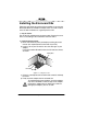
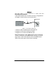
Installing the Eiconcard S9x Follow the steps below to install the Eiconcard S9x. If you want the Eiconcard S9x to be available to multiple users on a LAN, install it in the PC that will function as a gateway for the LAN. 1 Prepare the PC Turn off the PC and disconnect its power cable. Remove the cover of the PC according to the instructions that came with it. 2 Install the Eiconcard S9x Drain static electricity from your body by touching the metal chassis (the unpainted metal at the back of your PC).
screw PCI Eiconcard PCI slot Figure 2. Inserting the Eiconcard S9x. Fasten the adapter with the screw (to ensure that the adapter is properly secured and grounded to the PC’s chassis). f) Replace the cover of your PC as described in your PC’s manual. g) Reconnect the power cable. e) 3 Test the Eiconcard S9x The application software purchased with the Eiconcard S9x contains a test program to verify the card’s integrity. Consult the documentation supplied with this software for details.
Making an ISDN Connection Note Only the Eiconcard S91 supports ISDN connections. After you have installed your Eiconcard S91, connect your ISDN line. In Europe and most countries worldwide In Europe as well as most countries outside of North America and Japan, your Eiconcard S91 adapter can be connected directly to your ISDN line using the included cable. 1. ISDN wall jack Eiconcard S91 3. 2. Figure 3. Connecting the ISDN cable. 1 Take the cable included with the Eiconcard S91.
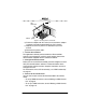
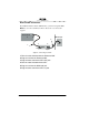
Eiconcard S91 U-interface: If your Eiconcard S91 has a U-interface, the NT1 is integrated into the adapter, and you do not need a separate NT1. 1. ISDN wall jack Eiconcard S91 3. 2. Figure 4. Connecting the ISDN cable. 1 Take the cable included with the Eiconcard S91. 2 Plug the RJ-45 end into the Eiconcard S91. 3 Plug the RJ-11 end into the ISDN wall jack. Note In North America, many ISDN wall jacks (with a U-interface) are RJ-11.
Eiconcard S91 S/T-interface: If your Eiconcard S91 has an S/T-interface, you need a separate NT1. Note You can order an NT1 from Eicon Networks or from another supplier. Eiconcard S91 ISDN wall jack 2. 4. 1. 3. 6. NT1 S/T jack U jack Figure 5. Connecting to an NT1. 1 Take the cable included with the Eiconcard S91. 2 Plug one end into the Eiconcard S91. 3 Plug the other end into the NT1’s S/T jack. 4 Take the cable included with the NT1. 5 Plug one end into the ISDN wall jack.
Termination This section applies to S/T interface users in Australia and North America, and provides instructions to help set up termination scenarios. Termination requirements vary according to: the number of devices connected to the NT1; and the distance between the devices and the NT1. For users who require termination, the Eiconcard S91 S/T has been shipped with a separate terminating resistor.
Multiple ISDN Devices If the NT1 is connected to more than one ISDN device, follow the procedures below. 75 meters or more If the connection spans 75 meters (250 feet) or more, both end devices on the ISDN bus must be set to 100 ohm termination. If the Eiconcard is one of the end devices, connect the 100 ohm terminating resistor included with the ISDN cable. Consult the manuals provided with the other ISDN devices and NT1 for more details.
Making a VHSI Connection The Eiconcard S9x can connect as a DTE to devices such as Data Service Units (DSUs) which support one of the following interfaces: V.24, V.35, EIA-530, V.36/RS-449, or X.21. It can also connect directly to a host computer, or back-to-back to another Eiconcard. Each VHSI port is configured independently Table 1 lists the most common connections supported by the VHSI port, and specifies the part number of the required Eicon Networks cable.
Interface Specifications The standards compliant with each interface supported on the VHSI port are listed in Table 2. The rest of this section describes the allocation of pins used to implement the electrical and signaling requirements of each interface. A wiring diagram is also provided, to show the correspondence of the interface pinout to the VHSI port. Interface Standard Compatibility V.24 CCITT V.24 Signaling V.35 EIA-530 V.36/RS-449 X.21 CCITT V.28 Electrical CCITT X.
Cable Construction Information If you plan to construct your own VHSI cables, be sure to observe the guidelines given below. Wire Gauge, Grounding, and Pairing • Use 28 AWG 7-strand wire with 0.020–0.028" insulation. • The chassis must be grounded both by a drain wire and by the braid; both must be connected to the connector case and shell at each end of the cable. The braid must be connected through its full circumference. • Wires identified under the heading “Twisted Pairs” must be paired.
The V.24 DCE Interface A pin-out diagram for the V.24 DCE interface is shown in Figure 6. The signal definitions and names are listed in Table 4. 1 PG N D TXD RXD RTS CTS DSR SG N D DCD 14 TCLK RCLK TEST DTR RLB RI DTECLK TI 25 13 Figure 6. V.
VHSI—V.24 Connections The wiring diagram below shows the connections required to construct a VHSI—V.24 DCE cable. For additional information required to construct your own cables, see “Cable Construction Information” on page 15. VHSI V.24 7 9 11 12 13 15 16 18 20 21 25 30 33 34 1 2 3 19 5 17 6 10 8 14 23 35 24 28 26 32 23 35 24 5 6 2 8 15 17 22 3 18 4 20 21 25 7 DRAIN WIRE 1 BRAID Figure 7. VHSI—V.24 DCE Connections The V.
The V.24 DTE Interface A pin-out diagram for the V.24 DTE interface is shown in Figure 8. The signal definitions and names are listed in Table 5. PGND TXD RXD RTS RTS DSR SGND DCD 1 14 RCLK RCLK DTR DTECLK 25 13 Figure 8. V.
VHSI—V.24 Connections The wiring diagram below shows the connections required to construct a VHSI—V.24 DTE cable. For additional information required to construct your own cables, see “Cable Construction Information” on page 15. VHSI V.24 7 17 15 8 9 25 11 12 13 20 3 4 5 24 16 15 20 30 1 2 3 19 2 6 7 DRAIN WIRE 1 BRAID Figure 9. VHSI—V.24 DTE Connections The V.
The V.35 Interface A pin-out diagram for the V.35 interface is shown in Figure 10. The signal definitions and names are listed in Table 6. SGND CTS DCD RI TEST RLB R XD + R XD R C LK + R C LK - B TI NN A P G ND RTS DSR DTR T X D+ TX DCLK+ CLKT CLK+ TCLK- MM Figure 10. V.
VHSI—V.35 Connections The wiring diagram below shows the connections required to construct a VHSI—V.35 cable. For additional information required to construct your own cables, see “Cable Construction Information” on page 15. TWISTED PAIRS (MANDATORY) VHSI V.35 Y AA R T V X P S U W D E F J L C H N NN B A 5 23 6 24 8 26 10 28 14 32 9 11 13 18 21 25 30 33 34 36 1 3 19 DRAIN WIRE BRAID Figure 11. VHSI—V.35 Connections The V.
The EIA-530 Interface A pin-out diagram for the EIA530 interface is shown in Figure 12. The signal definitions and names are listed in Table 7. PG ND TXD+ RXD+ RTS+ CTS+ DSR+ SG N D DCD+ RTXCDCDCL KTRXCCTS- 1 13 14 25 TXDTRXC+ RXDRTXC+ TEST RTSDTR+ RLB DSRDTRCLK+ TI Figure 12.
VHSI—EIA-530 Connections The wiring diagram below shows the connections required to construct a VHSI—EIA-530 cable. For additional information required to construct your own cables, see “Cable Construction Information” on page 15. TWISTED PAIRS (MANDATORY) VHSI EIA-530 4 22 5 23 6 24 7 25 8 26 9 27 11 29 12 30 13 31 17 35 21 33 34 1 2 19 2 14 15 12 3 16 4 19 17 9 5 13 6 22 20 23 8 10 24 11 18 21 25 7 1 DRAIN WIRE BRAID Figure 13.
The V.36/RS-449 Interface 1 PG N D TXD+ TRXC+ RXD+ RTS+ RTXC+ CTS+ TEST DSR+ DTR+ DCD+ RLB RI CLK+ TI GND A pin-out diagram for the V.36/RS-449 interfaces is shown in Figure 14. The signal definitions and names are listed in Table 8. 20 TXDTRXCRXDRTSRTXCCTSDSRDTRDCD- C LK - 19 37 Figure 14. V.
VHSI—V.36/RS-449 Connections The wiring diagram below shows the connections required to construct a VHSI—V.36/RS-449 cable. For additional information required to construct your own cables, see “Cable Construction Information” on page 15. TWISTED PAIRS (MANDATORY) VHSI V.36 / RS-449 4 22 5 23 6 24 7 25 8 26 9 27 11 29 12 30 13 31 17 35 18 21 33 34 1 2 19 4 22 5 23 6 24 7 25 8 26 9 27 11 29 12 30 13 31 17 35 15 10 14 18 19 20 37 DRAIN WIRE BRAID Figure 15. VHSI—V.36/RS-449 Connections The V.
The X.21 Interface 1 A pin-out diagram for the X.21 interface is shown in Figure 16. The signal definitions and names are listed in Table 9. PG N D T(A) C(A) R(A) I(A) S(A) B(A) SGND 9 T(B) C(B) R(B) I(B) S(B) B(B) PG ND 8 15 Figure 16. X.
VHSI—X.21 Connections The wiring diagram below shows the connections required to construct a VHSI—X.21 cable. For additional information required to construct your own cables, see “Cable Construction Information” on page 15. TWISTED PAIRS (MANDATORY) VHSI X.21 1 19 4 22 5 23 6 24 8 26 11 29 12 30 8 2 9 7 14 4 11 6 13 5 12 3 10 DRAIN WIRE 1 BRAID Figure 17. VHSI—X.21 Connections The X.
Back-to-Back Connections The wiring diagram below shows the connections required to construct a back-to-back VHSI—VHSI cable. Back-to-back operations are conducted through the V.36 interface. For additional information required to construct your own cables, see “Cable Construction Information” on page 15. TWISTED PAIRS (MANDATORY) VHSI VHSI 6 24 4 22 4 22 6 24 5 8 26 23 7 9 27 25 11 29 12 30 17 35 13 31 12 30 11 29 7 9 27 25 5 8 26 23 13 31 17 35 1 2 19 1 2 19 DRAIN WIRE BRAID Figure 18.
LED Functionality Eiconcard S90, S92, and S94 Note The Eiconcard S90 has only one VHSI port. Configuration Status This status light illuminates during configuration to indicate which card and/or port is being configured. This is most useful when more than one Eiconcard is installed in the PC. Consult the documentation provided with the configuration software for information about this status light.
Eiconcard S91 The Eiconcard S91 has three status lights (LEDs) on the end bracket. Two of these lights indicate the status of the ISDN connection, and the third identifies the card during configuration. D-channel Status The D-channel controls the link to your ISDN service provider. Off .......... The line is not active. The cable may not be connected. Blinking .. The line is active, but a link can’t be established. This may be a symptom of incorrect configuration. Steady....
Technical Specifications Technical Data • PCI bus compatible (32-bit slot) Eiconcard CPU/Memory/Flash Eiconcard S90 25 MHz Motorola 68302 / 1 MB RAM / 1 MB Flash # of VHSI Ports #of ISDN BRI Ports 1 N/A Eiconcard S91 25 MHz Motorola 68302 / 1 MB RAM / 1 MB Flash 1 1 Eiconcard S92 33 MHz Motorola 68360 / 1 MB RAM / 1 MB FLASH 2 N/A Eiconcard S94 33 MHz Motorola 68360 / 8 MB RAM / 1 MB FLASH 2 N/A Hardware Installation • Automatic configuration of interrupt request level setting and I/O addr
VHSI Ports • • • • VHSI ports connect to 36-pin high-density male connectors Support for V.24, V.35, EIA-530, and V.36/RS-449 X.21 with V.11 (X.27) signaling Internal or external clocking (DTE or DCE) or split (transmit internal, receive external) Power Consumption Warning: Check that power supply will not be overloaded. Maximum power consumption of the board is stated above.
International Regulatory Information Regulatory Information for the USA: WARNING. Changes or modifications to this unit not expressly approved by Eicon Networks Corporation could void the user's authority to operate the equipment.
FCC Part 68 Notice This unit complies with Part 68 of the FCC rules. On the bottom of this equipment is a label that contains, among other information, the FCC registration number. If requested, this information must be provided to the telephone company. An FCC compliant telephone cord and modular plug is provided with this equipment, designed to be connected to the telephone network or premises wiring using a compatible modular jack which is Part 68 compliant.
Regulatory Information for Canada NOTICE: The Industry Canada label identifies certified equipment. This certification means that the equipment meets certain telecommunications network protective, operational and safety requirements. Industry Canada does not guarantee the equipment will operate to the user’s satisfaction. Before installing this equipment, users should ensure that it is permissible to be connected to the facilities of the local telecommunications company.
Regulatory Information for Europe EU Declaration of Conformity EN: Eicon Networks Corporation declares that this equipment is in compliance with the essential requirements and other relevant provisions of Directive1999/5/EC. DE: Eicon Networks Corporation erklärt, daß diese Telekommunikations-endeinrichtung den grundlegenden Anforderungen und anderen relevanten Bestimmungen der Richtlinie 1999/5/EG entspricht.
Safety Status: SELV No voltages within this equipment exceed SELV voltages. All interconnection points and ports are SELV. User/Installer Instructions for the United Kingdom Important Safety Considerations When Installing Into A Host Computer System The Eiconcard S9x is a single PCI card.
Regulatory information for Australia • This customer equipment shall only be installed in a PC that requires the use of a tool to gain access to internal parts (e.g. this customer equipment must not be installed in a PC with a ‘flip lid’). • Proper installation of the Eiconcard S9x card requires that it is screwed to the metal backplate of the computer. This ensures proper grounding, which is necessary for safety purposes.
203-227-01