64-0308-09.fm Page 1 Monday, March 15, 2010 3:32 PM Eiconcard™ Family Installation Guide for PCI and PCI Express Compatible Bus www.dialogic.
64-0308-09.fm Page 2 Monday, March 15, 2010 3:32 PM Copyright © 2001-2010 Dialogic Corporation. All Rights Reserved. You may not reproduce this document in whole or in part without permission in writing from Dialogic Corporation at the address provided below. All contents of this document are furnished for informational use only and are subject to change without notice and do not represent a commitment on the part of Dialogic Corporation or its subsidiaries ("Dialogic").
64-0308-09.fm Page 3 Monday, March 15, 2010 3:32 PM UNOPENED "AS NEW" CONDITION (INCLUDING ALL DOCUMENTATION AND BINDERS OR OTHER CONTAINERS) FOR A FULL REFUND AND/OR YOU SHOULD NOT COMMENCE THE APPLICABLE DOWNLOADING.
64-0308-09.fm Page 4 Monday, March 15, 2010 3:32 PM • You may transfer the Program, documentation and the license to another eligible party within Your Company if the other party agrees to accept the terms and conditions of this Agreement.
64-0308-09.fm Page 5 Monday, March 15, 2010 3:32 PM or other pecuniary loss and indirect, punitive, incidental, economic, consequential or special damages, arising out of or in connection with this Agreement and/or the use, inability to use the Program and/or the Program's performance or inability to perform nor from or in connection with the Program's accompanying documentation, or any data or equipment related thereto or used in connection therewith.
4-0308-09.fm Page 6 Monday, March 15, 2010 3:32 PM be sent by registered mail or courier to the attention of Dialogic's legal department at the address below or such other address as may be listed on www.dialogic.com from time to time as being Dialogic's Montreal headquarters. U.S. Government Restricted Rights The Program and all accompanying documentation are provided with RESTRICTED RIGHTS. Use, duplication or disclosure by the U.S.
64-0308-09.fm Page 7 Monday, March 15, 2010 3:32 PM Contents Introduction .................................................................... 9 Eiconcard C series ...................................................................... 9 Eiconcard S series ...................................................................... 9 Installing the Eiconcard ................................................. 11 Making an ISDN connection ...........................................
64-0308-09.fm Page 8 Monday, March 15, 2010 3:32 PM Technical specifications Eiconcard S series ......................................................... 39 Technical data ......................................................................... Hardware installation................................................................ Performance............................................................................ Environmental requirements......................................................
64-0308-09.fm Page 9 Monday, March 15, 2010 3:32 PM Eiconcard™ Family Installation Guide Introduction This booklet describes the Dialogic® Eiconcard™ C and S series interface cards. All Eiconcards have been tested and found to comply with the Electromagnetic compatibility, Safety and Network connection regulations within the European Union, North America, and other major territories. Read the regulatory information on page 41 before installing and using your product.
64-0308-09.fm Page 10 Monday, March 15, 2010 3:32 PM Introduction and an ISDN BRI port, supporting line speeds up to 2 Mbps (T1/E1) and 128 kbps respectively. The Eiconcard S Series allows you to connect using WAN protocols such as X.25, Frame Relay, PPP, SDLC and HDLC, over leased lines, dial-up lines or ISDN lines.
64-0308-09.fm Page 11 Monday, March 15, 2010 3:32 PM Eiconcard™ Family Installation Guide Installing the Eiconcard If you want the Eiconcard to be available to multiple users on a LAN, install it in the computer that will function as a gateway for the LAN. 1 Prepare the computer Turn off the computer and disconnect its power cable. Wait at least 30 seconds to ensure that all power has drained from the system. Remove the cover of the computer according to the instructions that came with it.
64-0308-09.fm Page 12 Monday, March 15, 2010 3:32 PM Installing the Eiconcard Bracket retaining screw Bracket jackposts c) Insert the Eiconcard into the slot and fasten it with a screw. 3 Test the Eiconcard The application software available for the Eiconcard contains a test program to verify the Eiconcard’s integrity. Consult the documentation supplied with this software for details.
64-0308-09.fm Page 13 Monday, March 15, 2010 3:32 PM Eiconcard™ Family Installation Guide 4 Configure the Eiconcard Before you can use the Eiconcard, you must configure it to work with your communications software. Consult the documentation supplied with this software for complete instructions on how to configure the Eiconcard. 5 Connect to your external line You are now ready to connect the Eiconcard to your external line.
64-0308-09.fm Page 14 Monday, March 15, 2010 3:32 PM Making an ISDN connection Making an ISDN connection Before you connect the Eiconcard, check with your ISDN provider to determine if you need an NT1 to terminate your ISDN line. In some countries, the NT1 is installed by your ISDN provider and resides in the central switching office. In other countries, the NT1 must be installed at your premises, either by you or your ISDN provider. You can order an NT1 from Dialogic or from another supplier.
64-0308-09.fm Page 15 Monday, March 15, 2010 3:32 PM Eiconcard™ Family Installation Guide Termination This section provides instructions to help set up termination scenarios for installations in Australia and North America. Termination requirements vary according to the number of ISDN devices connected to the NT1 and the distance between the ISDN devices and the NT1. Terminating resistor If you purchased the Eiconcard in North America, a 100 ohm terminating resistor is included.
64-0308-09.fm Page 16 Monday, March 15, 2010 3:32 PM Making a VHSI connection Making a VHSI connection (S series Eiconcards only) The VHSI port can be used to connect the Eiconcard as a DTE to devices such as Data Service Units (DSUs) that support one of the following interfaces: V.24, V.35, EIA-530, V.36/RS-449, or X.21. It can also be used to connect the Eiconcard directly to a host computer, or back-to-back with a VHSI port on another Eiconcard.
64-0308-09.fm Page 17 Monday, March 15, 2010 3:32 PM Eiconcard™ Family Installation Guide Making a V.24 Connection (C series Eiconcards only) The V.24 port can be used to connect the Eiconcard as a DTE to devices that support a V.24 interface, directly to a host computer, or back-to-back with a V.24 port on another Eiconcard. Consult the documentation which came with your networking software for more information about port configuration. V.
64-0308-09.fm Page 18 Monday, March 15, 2010 3:32 PM Status lights Eiconcard C90, C91 S/T, C91 V2, and C91 PCIe LP Status lights Eiconcard C90, C91 S/T, C91 V2, and C91 PCIe LP ISDN D-channel Status (Eiconcard C91 S/T, C91 V2, and C91 PCIe LP only) The D-channel controls the link to your ISDN service provider. Off........... The line is not active. The cable may not be connected. ISDN port Blinking.... The line is active, but a link cannot be established.
64-0308-09.fm Page 19 Monday, March 15, 2010 3:32 PM Eiconcard™ Family Installation Guide Status Lights Eiconcard S91 S/T and S91 V2 ISDN D-channel status The D-channel controls the link to your ISDN service provider. Off .........The line is not active. The cable may not be connected. ISDN port Blinking ..The line is active, but a link cannot be established. This may be a symptom of incorrect configuration. Steady ...The ISDN line is active and operating normally.
64-0308-09.fm Page 20 Monday, March 15, 2010 3:32 PM Status Lights Eiconcard S90, S92, S94, S94/66 MHz, S94 V2, and S94 PCIe Status Lights Eiconcard S90, S92, S94, S94/66 MHz, S94 V2, and S94 PCIe Configuration status This status light illuminates when the Eiconcard and/or port is being configured. VHSI port Consult the documentation provided with the configuration software for information about this status light.
64-0308-09.fm Page 21 Monday, March 15, 2010 3:32 PM Eiconcard™ Family Installation Guide VHSI port specifications Each interface on the VHSI port is compliant with the standards listed in Table 1. The rest of this section describes the pinouts that are used to implement the electrical and signaling requirements of each interface. A wiring diagram is also provided for each interface that describes how interface pinouts are mapped to the VHSI port. Interface Standard Compatibility V.24 CCITT V.
64-0308-09.fm Page 22 Monday, March 15, 2010 3:32 PM VHSI port specifications Cable construction information If you plan to construct your own VHSI cables, be sure to observe the guidelines given below. Wire gauge, grounding, and pairing • Use 28 AWG 7-strand wire with 0.020 - 0.028" insulation. • The chassis must be grounded both by a drain wire and by the braid; both must be connected to the connector case and shell at each end of the cable. The braid must be connected through its full circumference.
64-0308-09.fm Page 23 Monday, March 15, 2010 3:32 PM Eiconcard™ Family Installation Guide V.24 DCE interface A pin-out diagram for the V.24 DCE interface is shown in Figure 1. The signal definitions and names are listed in Table 3. PG N D TXD RXD RTS CTS DSR SG N D DCD 1 14 TCLK RCLK TEST DTR RLB RI DTECLK TI 25 13 Figure 1. V.
64-0308-09.fm Page 24 Monday, March 15, 2010 3:32 PM VHSI port specifications VHSI—V.24 connections The wiring diagram in Figure 2 shows the connections required to construct a VHSI—V.24 DCE cable. For additional information required to construct your own cables, see “Cable construction information” on page 22. VHSI V.24 7 9 11 12 13 15 16 18 20 21 25 30 33 34 1 2 3 19 5 17 6 10 8 14 23 35 24 28 26 32 24 5 6 2 8 15 17 22 3 18 4 20 21 25 7 DRAIN WIRE BRAID Figure 2. VHSI—V.
64-0308-09.fm Page 25 Monday, March 15, 2010 3:32 PM Eiconcard™ Family Installation Guide V.24 DTE interface A pin-out diagram for the V.24 DTE interface is shown in Figure 3. The signal definitions and names are listed in Table 4. PGND TXD RXD RTS RTS DSR SGND DCD 1 14 RCLK RCLK DTR DTECLK 25 13 Figure 3. V.
64-0308-09.fm Page 26 Monday, March 15, 2010 3:32 PM VHSI port specifications VHSI—V.24 connections The wiring diagram in Figure 4 shows the connections required to construct a VHSI—V.24 DTE cable. For additional information required to construct your own cables, see “Cable construction information” on page 22. VHSI V.24 7 17 15 8 9 25 11 12 13 20 3 4 5 24 16 15 20 30 1 2 3 19 2 6 7 DRAIN WIRE BRAID Figure 4. VHSI—V.
64-0308-09.fm Page 27 Monday, March 15, 2010 3:32 PM Eiconcard™ Family Installation Guide V.35 interface A pin-out diagram for the V.35 interface is shown in Figure 5. The signal definitions and names are listed in Table 5. SGND CTS DCD RI TEST RLB R XD + R XD R C LK + R C LK - B TI NN A P G ND RTS DSR DTR T X D+ TX DCLK+ CLKT CLK+ TCLK- MM Figure 5. V.
64-0308-09.fm Page 28 Monday, March 15, 2010 3:32 PM VHSI port specifications VHSI—V.35 connections The wiring diagram in Figure 6 shows the connections required to construct a VHSI—V.35 cable. For additional information required to construct your own cables, see “Cable construction information” on page 22. TWISTED PAIRS (MANDATORY) VHSI V.35 Y AA R T V X P S U W D E F J L C H N NN B A 5 23 6 24 8 26 10 28 14 32 9 11 13 18 21 25 30 33 34 36 1 3 19 DRAIN WIRE BRAID Figure 6. VHSI—V.
64-0308-09.fm Page 29 Monday, March 15, 2010 3:32 PM Eiconcard™ Family Installation Guide EIA-530 interface A pin-out diagram for the EIA-530 interface is shown in Figure 7. The signal definitions and names are listed in Table 6. PG ND TXD+ RXD+ RTS+ CTS+ DSR+ SG N D DCD+ RTXCDCDCL KTRXCCTS- 1 13 14 25 TXDTRXC+ RXDRTXC+ TEST RTSDTR+ RLB DSRDTRCLK+ TI Figure 7.
64-0308-09.fm Page 30 Monday, March 15, 2010 3:32 PM VHSI port specifications VHSI—EIA-530 connections The wiring diagram in Figure 8 shows the connections required to construct a VHSI—EIA-530 cable. For additional information required to construct your own cables, see “Cable construction information” on page 22.
64-0308-09.fm Page 31 Monday, March 15, 2010 3:32 PM Eiconcard™ Family Installation Guide V.36/RS-449 interface A pin-out diagram for the V.36/RS-449 interfaces is shown in Figure 9. The signal definitions and names are listed in Table 7. 1 PG N D TXD+ TRXC+ RXD+ RTS+ RTXC+ CTS+ TEST DSR+ DTR+ DCD+ RLB RI CLK+ TI GND 20 TXDTRXCRXDRTSRTXCCTSDSRDTRDCD- C LK - 19 37 Figure 9. V.
64-0308-09.fm Page 32 Monday, March 15, 2010 3:32 PM VHSI port specifications VHSI—V.36/RS-449 connections The wiring diagram in Figure 10 shows the connections required to construct a VHSI—V.36/RS-449 cable. For additional information required to construct your own cables, see “Cable construction information” on page 22. TWISTED PAIRS (MANDATORY) VHSI V.
64-0308-09.fm Page 33 Monday, March 15, 2010 3:32 PM Eiconcard™ Family Installation Guide X.21 interface A pin-out diagram for the X.21 interface is shown in Figure 11. The signal definitions and names are listed in Table 8. 1 PG N D T(A) C(A) R(A) I(A) S(A) B(A) SGND 9 T(B) C(B) R(B) I(B) S(B) B(B) PG ND 8 15 Figure 11. X.
64-0308-09.fm Page 34 Monday, March 15, 2010 3:32 PM VHSI port specifications VHSI—X.21 connections The wiring diagram in Figure 12 shows the connections required to construct a VHSI—X.21 cable. For additional information required to construct your own cables, see “Cable construction information” on page 22. TWISTED PAIRS (MANDATORY) VHSI X.21 1 19 4 22 5 23 6 24 8 26 11 29 12 30 8 2 9 7 14 4 11 6 13 5 12 3 10 DRAIN WIRE BRAID Figure 12. VHSI—X.
64-0308-09.fm Page 35 Monday, March 15, 2010 3:32 PM Eiconcard™ Family Installation Guide Back-to-back connections The wiring diagram in Figure 13 shows the connections required to construct a back-to-back VHSI—VHSI cable. Back-to-back operations are conducted through the V.36 interface. For additional information required to construct your own cables, see “Cable construction information” on page 22.
64-0308-09.fm Page 36 Monday, March 15, 2010 3:32 PM V.24 port specifications V.24 port specifications V.24 DCE Interface The V.24 port is wired as a V.24 DCE interface as shown in Figure 14 for the Eiconcard C90, C91 S/T, and C91 V2, and Figure 15 for the Eiconcard C91 PCIe LP. The signal definitions and names are listed in Table 9. PG N D TXD RXD RTS CTS DSR SG N D DCD 1 14 TCLK RCLK TEST DTR RLB RI DTECLK TI SGND DSR CTS RTS RXD RLB RCLK TCLK 25 13 Figure 14. DB-25 female connector X.
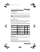
64-0308-09.fm Page 37 Monday, March 15, 2010 3:32 PM Eiconcard™ Family Installation Guide Technical specifications Eiconcard C series Technical data Model CPU/Memory/ Flash V.24 Ports ISDN BRI Ports Connector Key PCI Bus (up to) Eiconcard C90 16 MHz Motorola 1 68302 / 512 KB RAM / 512 KB Flash N/A 5V 2.1 32 bits 33 MHz Eiconcard C91 S/T 1 16 MHz Motorola 68302 / 512 KB RAM / 512 KB Flash 1 5V 2.
64-0308-09.fm Page 38 Monday, March 15, 2010 3:32 PM Technical specifications Eiconcard C series Power Requirements Eiconcard +5V +12V -12V Eiconcard C90 1A 50 mA 50 mA Eiconcard C91 S/T 1A 50 mA 50 mA Eiconcard C91 V2 .5 A 50 mA 50 mA Eiconcard C91 PCIe LP N/A 400 mA N/A Note The Eiconcard C91 PCIe LP does not use 3.3V power and always draws less than 10W from the bus connector supply. Power Consumption Warning: Ensure that the power supply will not be overloaded.
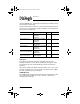
64-0308-09.fm Page 39 Monday, March 15, 2010 3:32 PM Eiconcard™ Family Installation Guide Technical specifications Eiconcard S series Technical data Model CPU/Memory/ Flash VHSI Ports ISDN BRI Ports Connector Key PCI Eiconcard S90 25 MHz Motorola 68302 /1 MB RAM / 1 MB Flash 1 N/A 5V 2.1 32 bits 33 MHz Eiconcard S91 S/T 25 MHz Motorola 68302 / 1 MB RAM / 1 MB Flash 1 1 5V 2.1 32 bits 33 MHz Eiconcard S91 V2 50 MHz Motorola 855T / 8MB SDRAM 1 1 3.3V or 5V 2.
64-0308-09.fm Page 40 Monday, March 15, 2010 3:32 PM Technical specifications Eiconcard S series External interface Model External Interface Eiconcard S90 One 36-pin “D Type” female ports. Eiconcard S91S/T One 36-pin “D Type” female port and one RJ-45 port. Eiconcard S91 V2 One 36-pin “D Type” female port and one RJ-45 port. Eiconcard S92 Two 36-pin “D Type” female ports. Eiconcard S94 Two 36-pin “D Type” female ports. Eiconcard S94/66 MH Two 36-pin “D Type” female ports.
64-0308-09.fm Page 41 Monday, March 15, 2010 3:32 PM Eiconcard™ Family Installation Guide International regulatory information Regulatory information for the USA WARNING. Changes or modifications to this unit not expressly approved by Dialogic Corporation could void the user's authority to operate the equipment.
64-0308-09.fm Page 42 Monday, March 15, 2010 3:32 PM International regulatory information A plug and jack used to connect this equipment to the premises wiring and telephone network must comply with the applicable FCC part 68 rules and requirements adopted by the ACTA. A compliant telephone cord and modular plug is provided with this product. It is designed to be connected to a compatible modular jack that is also compliant.
64-0308-09.fm Page 43 Monday, March 15, 2010 3:32 PM Eiconcard™ Family Installation Guide Regulatory information for Canada NOTICE: This equipment meets the applicable Industry Canada Terminal Equipment Technical Specifications. This is confirmed by the registration number. The abbreviation, IC: , before the registration number signifies that registration was performed based on a Declaration of Conformity indicating that Industry Canada technical specifications were met.
64-0308-09.fm Page 44 Monday, March 15, 2010 3:32 PM International regulatory information Regulatory information for Europe EU declaration of conformity Dialogic Corporation declares that this equipment is in compliance with the Radio and Telecommunication Terminal Equipment directive 1999/5/EC with requirements covering the Electromagnetic Compatibility Directive 89/336/EEC and the Low Voltage Directive 2006/95/EC. A detailed declaration of conformity for this product can be found at: http://www.
64-0308-09.fm Page 45 Monday, March 15, 2010 3:32 PM Eiconcard™ Family Installation Guide PT: Dialogic declara que este ITE está conforme com os requisitos essenciais e outras disposições da Directiva 1999/5/CE. SL: Dialogic izjavlja, da je ta ITE v skladu z bistvenimi zahtevami in ostalimi relevantnimi doloèili direktive 1999/5/ES. SK: Dialogic týmto vyhlasuje, že ITE spåòa základné požiadavky a všetky príslušné ustanovenia Smernice 1999/5/ES.
64-0308-09.fm Page 46 Monday, March 15, 2010 3:32 PM International regulatory information Regulatory information for Australia WARNING This customer equipment is to be installed and maintained by service personnel as defined by AS/NZS 3260 Clause 1.2.14.3 Service Personnel. It may be hazardous if your computer is not properly plugged in and grounded. IMPORTANT This equipment will be inoperable when mains power fails.
64-0308-09.fm Page 47 Monday, March 15, 2010 3:32 PM Declaration of Conformity No: D0023 Revision 01 The equipment described below is declared to be in conformity with the following applicable national and international standards. The conformity is valid ONLY when the equipment is used in a manner consistent with the manufacturer’s recommendations and the reference documents.
64-0308-09.fm Page 48 Monday, March 15, 2010 3:32 PM Declaration of Conformity No: D0024 Revision 01 The equipment described below is declared to be in conformity with the following applicable national and international standards. The conformity is valid ONLY when the equipment is used in a manner consistent with the manufacturer’s recommendations and the reference documents.
64-0308-09.fm Page 49 Monday, March 15, 2010 3:32 PM Declaration of Conformity No: D0025 Revision 01 The equipment described below is declared to be in conformity with the following applicable national and international standards. The conformity is valid ONLY when the equipment is used in a manner consistent with the manufacturer’s recommendations and the reference documents.
64-0308-09.fm Page 50 Monday, March 15, 2010 3:32 PM Declaration of Conformity No: D0026 Revision 01 The equipment described below is declared to be in conformity with the following applicable national and international standards. The conformity is valid ONLY when the equipment is used in a manner consistent with the manufacturer’s recommendations and the reference documents.
64-0308-09.fm Page 51 Monday, March 15, 2010 3:32 PM Declaration of Conformity No: D0087 Revision 01 The equipment described below is declared to be in conformity with the following applicable national and international standards. The conformity is valid ONLY when the equipment is used in a manner consistent with the manufacturer’s recommendations and the reference documents.
64-0308-09.fm Page 52 Monday, March 15, 2010 3:32 PM Copyright © 2001-2010 Dialogic Corporation www.dialogic.com All rights reserved.