
Instruction manual


INTUITY Messaging Solutions Release 4
MAP/5P Maintenance
585-310-186
Issue 3
October 1997
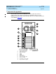
System Configuration
Page A-8Component Assignments
A
Resource Allocation
Ta b l e A - 3 lists the resource assignments for all devices in the MAP/5P. It includes
the circuit cards as well as devices which are included.
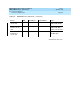
Table A-3. MAP/5P Resource Allocation
Device IRQ I/O Address RAM Address Notes
VGA controller - Plug & Play A0000-BFFFF
C0000-C7FFF
128 Kbyte video
RAM required
32 Kbyte video
BIOS required
System BIOS - - E0000-FFFF Located on CPU,
required
LPT1 port 7 378-37F - Located on CPU,
required
COM1 port 4 3F8-3FF - Located on CPU,
required
COM2 port 3 2F8-2FF - Disable for remote
maintenance circuit
card
PCI SCSI 14 Plug & Play C8000-CBFFF SCSI ID 7, required
2-Gbyte SCSI
disk
- - - 1 required, 1
optional
2-Gbyte SCSI
tape
- - - SCSI ID 3, 1
required
Diskette drive 6 3F0-3F7 - DMA 2, controller
located on SCSI
controller card,
required
LAN circuit card 10 280-29F D8000-D9FFF 1 optional
Multi-port circuit
card
- - D0000-D3FFF 1 optional
Tip/Ring circuit
card
2 x00-x1F - x=1-3;
1 required, 2
optional
ACCX circuit card 5 140-14F - 1 optional
Continued on next page