
Instruction manual


INTUITY Messaging Solutions Release 4
MAP/5P Maintenance
585-310-186
Issue 3
October 1997
System Configuration
Page A-7Component Assignments
A
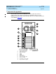
■ If any ISA slots are unoccupied, they should be between the set of
Tip/Ring and ACCX circuit cards and the set of LAN, switch interface, and
multi-port serial circuit cards.
The following tables outline the variable slot locations for optional circuit cards
when all of the available slots are to be filled. Each column, with the addition of
the required cards listed in “Fixed Assignments” above, is a configuration. In
Ta b l e A - 1
, for example, the first column represents a configuration that includes
seven Tip/Ring circuit cards in slots 4 through 6, no other optional circuit cards.
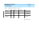
Ta b l e A - 1
lists the variable slot locations for configurations with multiple Tip/Ring
circuit cards and one other optional circuit card.
Ta b l e A - 1 lists the variable slot locations for configurations with Tip/Ring circuit
cards and multiple other optional circuit cards.
Table A-1. Variable Slot Assignments When System is Equipped with
Tip/Ring Circuit Cards and One other Optional Circuit Card
Circuit Card Slots Slots Slots Slots Slots
Tip/Ring 4-6 4-6 4-6 4-6 4-6
ACCX (AYC22) - 3 - - -
LAN --3--
Multi-port serial - - - 3 -
Switch Interface - - - - 3
Table A-2. Variable Slot Assignments When System is Equipped with Tip/Ring Circuit
Cards and Multiple other Optional Circuit Cards
Circuit
Card Slots Slots Slots Slots Slots Slots Slots Slots Slots Slots
Tip/Ring 5-6 5-6 5-6 5-6 5-6 5-6 6 6 6 6
ACCX
(AYC22)
444- - - 555-
LAN 3- - 33- 33- 3
multi-port
serial
--34-44-45
Switch
interface
-3--43-434