
Instruction manual


INTUITY Messaging Solutions Release 4
MAP/5P Maintenance
585-310-186
Issue 3
October 1997
System Configuration
Page A-6Component Assignments
A
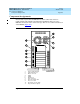
Fixed Assignments
The following bay assignments are fixed in the MAP/5P:
■ Bay 1 — Cartridge Tape drive
■ Bay 2 — Empty
■ Bay 3 — Empty
■ Bay 4 — Diskette drive
■ Bay 5 — Hard Disk Drive 1 (if provided)
■ Bay 6 — Hard Disk Drive 0
■ Bay 7 — Empty
The following slot assignment is fixed in the MAP/5P:
■ PCI Slot 1 — SCSI controller circuit card
■ ISA Slot 2 — remote maintenance circuit card
Variable Assignments
The Tip/Ring, ACCX, LAN, Multi-port, and switch interface circuit cards all have
variable assignments in the MAP/5P. These assignments depend on how many
cards have been installed. The following rules apply to the placement of optional
cards in the MAP/5P. These rules presume that the required circuit cards are
placed in the MAP/5P as specified in “Fixed Assignments” above.
■ A maximum of three Tip/Ring circuit cards is supported.
■ All other circuit cards are supported as one per system.
■ Tip/Ring circuit cards are assigned slots sequentially, starting, at the
bottom, with slot 6.
■ The ACCX circuit card is assigned in the lowest numbered available slot
after all Tip/Ring circuit cards have been installed. For example, if
Tip/Ring circuit cards are installed in ISA Slot 5 and ISA Slot 6, place the
ACCX circuit card in ISA Slot 4.
■ The LAN circuit card, if provided, goes in the lowest numbered available
ISA slot.
■ The switch interface circuit card, if provided, goes in the lowest numbered
available ISA slot after the LAN circuit card, if provided, has been
installed.
■ The multi-port serial circuit card, if provided, goes in the lowest numbered
ISA slot after both the LAN and switch interface circuit cards, if provided,
have been installed.