
Instruction manual


INTUITY Messaging Solutions Release 4
MAP/5P Maintenance
585-310-186
Issue 3
October 1997
System Configuration
Page A-4Component Assignments
A
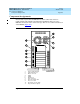
Operating hardware is placed in the MAP/5P in locations called
bays
. Bays are
numbered 1 through 7. Bays 1 through 5 are accessible from the front of the
MAP/5P (Figure A-3
).
Figure A-3. Front View of the MAP/5P
Bays 6 and 7 are accessible only after the dress cover has been removed
(Figure A-4
).
1. INT drive indicator
2. Speed indicator
3. Power indicator