
Instruction manual


INTUITY Messaging Solutions Release 4
MAP/5P Maintenance
585-310-186
Issue 3
October 1997
Replacing Other Components
Page 7-40Riser Card Replacement
7
Accessing the Riser Card
To access the riser card, do the following:
1. Remove the dress cover. See “Removing the Dress Cover
” in Chapter 4,
‘‘Getting Inside the Computer’’,” for this procedure.
2. Remove all of the circuit cards. See “Removing a Circuit Card
” in Chapter
5, ‘‘Replacing or Installing Circuit Cards’’,” for this procedure.
NOTE:
Pay close attention to the riser card connector slots from which each
circuit card is removed. The circuit cards will need to be replaced in
the same slots in the new riser card. See ‘‘Component Assignments’’
in Appendix A, ‘‘System Configuration’’
, for circuit card placement.
Extracting the Riser Card
To extract the riser card, do the following:
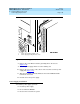
1. Remove the screw in the lower left corner of the riser card (Figure 7-14
).
2. Gently pull the riser card away from the motherboard until the riser card
connector is removed from the slot on the motherboard.
3. Continue with the next procedure, “Riser Card Installation
.”
Riser Card Installation
To install the riser card, you must:
■ Insert the riser card.
■ Re-assemble the MAP/5P.
■ Restore the Lucent INTUITY system.
Inserting the Riser Card
To insert the riser card, do the following:
1. Remove the new riser card from its ESD protective wrapping.
NOTE:
Keep the package and all ESD-protective wrapping to return the
defective unit. Re-use of the original replacement unit packaging is
necessary to meet the manufacturer’s warranty.
2. Align the riser card connector with the slot on the motherboard.
3. Gently push the riser card connector into the motherboard.
4. Replace the screw in the bottom left corner of the riser card (Figure 7-14
).